When a high-voltage transmission line experiences a fault, the protection relay must detect it and trip the breaker within milliseconds. If the relay fails to operate correctly — either missing a trip or tripping unnecessarily — the consequences range from equipment damage to widespread outages. A protection relay tester is the tool that verifies these relays will perform as intended, before a real fault occurs.
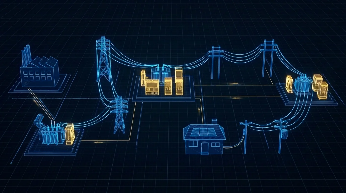
A protection relay tester, also called a relay test set, is a specialized instrument designed to validate the performance of protection relays in power systems. Its core mission: confirm that a relay trips when it should and does not trip when it should not. The tester achieves this by injecting precisely controlled voltage and current signals into the relay’s secondary inputs, simulating real-world fault conditions.
Where Protection Relay Testers Are Used
Relay test sets are used across the full power system lifecycle. Commissioning teams verify settings and wiring before new substations are energized. Maintenance programs run annual or biennial tests to catch component drift and degradation. Post-fault analysis replays disturbance recordings through relays to confirm correct response. Manufacturers validate relay performance during factory acceptance testing.
These functions span generation plants, transmission and distribution substations, industrial power systems, railway traction, data centers, and renewable energy installations including wind and solar farms.
How a Protection Relay Tester Works
Protection relay testers operate on the principle of secondary injection testing. Unlike primary injection, which requires high currents through the entire primary circuit including CTs and breakers, secondary injection connects the tester directly to the relay’s secondary inputs. This method is safer, more portable, and the standard approach for routine relay calibration.
The testing process follows four steps:
First, the tester generates a simulated fault waveform using its internal signal generation hardware. For an overcurrent test, the current ramps from zero to a preset level. For a distance relay test, it applies precise combinations of voltage and current to place the fault at a specific impedance point on the relay’s characteristic curve.
Second, the signal is injected into the relay’s input terminals through test leads. A typical tester provides multiple independent output channels — commonly three or six voltage and current channels — allowing simultaneous three-phase simulation. The relay processes these signals as if they came from real CTs and PTs.
Third, the tester measures the relay’s response in real time. Built-in timers capture the operating time from fault onset to trip signal, while binary inputs record contact state changes. Modern testers achieve measurement resolution down to tens of microseconds.
Fourth, the tester compares measured results against expected values. For an inverse-time overcurrent relay, it plots trip time against current magnitude and checks this against the IEEE or IEC characteristic curve. Any deviation beyond acceptable tolerance signals a problem that needs investigation.

Key Capabilities of a Protection Relay Tester
Comprehensive Fault Simulation
A capable relay test set simulates the full range of power system faults: phase and ground short circuits, overcurrent and overvoltage, frequency deviations, and three-phase unbalance. For transformer differential protection, six-phase testers inject currents simultaneously into both winding sets, replicating the through-fault and internal-fault conditions the relay must distinguish.
Precise Timing and Characteristic Measurement
Relay operating time is the single most critical parameter in protection coordination. The tester must measure this with sub-millisecond precision. Beyond timing, it automatically plots characteristic curves: the inverse-time curve of an overcurrent relay, the R-X diagram of a distance relay, or the percentage restraint characteristic of a differential relay. Comparing the measured curve against set points reveals drift or calibration errors before they cause operational issues.
Automated Test Sequences
Modern testers support pre-configured test plans that execute complete sequences with one command. For a standard overcurrent relay, an automated plan might step through multiple current multiples, record each trip time, verify the curve shape, and check the reset time — all without operator intervention between steps. Automated testing reduces effort by up to 80% while improving consistency and repeatability.
Multi-Generation Relay Compatibility
Protection relays span three technology generations: electromechanical, solid-state, and numerical. Electromechanical relays require higher drive current due to their induction disk mechanism. Numerical relays demand precise waveform fidelity and communication protocol support. A well-designed tester must handle all three generations without compromise.
IEC 61850 Support for Digital Substations
IEC 61850 is the international communication standard for digital substations. It defines how protection relays, merging units, and bay controllers exchange data using protocols like GOOSE (Generic Object-Oriented Substation Event) for fast peer-to-peer communication and Sampled Values (IEC 61850-9-2) for digitized CT and PT measurements. Testers with IEC 61850 capability can inject Sampled Value streams directly into numerical relays and verify GOOSE-based tripping schemes, which is essential for modern substation commissioning.
How to Choose a Protection Relay Tester for Beginners
For first-time buyers, the selection process comes down to a few critical specifications.
Accuracy: The DAC Matters
Measurement accuracy should be Class 0.2 or better (error ≤ ±0.2% of reading + 1 digit). The resolution of the digital-to-analog converter (DAC) is the hardware factor that determines real-world accuracy. Industry-standard testers use 16-bit DACs. Some products advertise “high accuracy” while using 8-bit DACs that produce output distortion exceeding 5% under certain conditions. Always verify the DAC specification and request an accuracy report across the 0–120% rated range.
Continuous vs. Peak Output Current
The difference between “maximum current” and “continuous current” is where many beginners get misled. A tester rated for 100 A peak may only sustain 30 A continuously. For realistic protection testing, look for at least 30 A continuous per phase with three-phase parallel capability of 90 A or more. Voltage output should be at least 125 V continuous per phase with less than 2% drop under rated load.
Three-Phase or Six-Phase
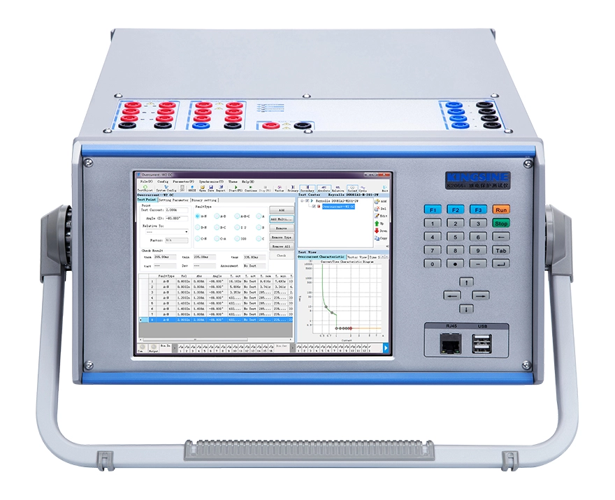
A three-phase tester (3 current + 3–4 voltage channels) covers most standard protection types: overcurrent, overvoltage, undervoltage, directional, and simple distance protection. It is lighter, more affordable, and sufficient for general-purpose field work.
A six-phase tester (6 current + 4–6 voltage channels) becomes necessary when testing transformer differential protection, where both winding sets must be energized simultaneously. It also supports advanced IEC 61850 schemes. Choose based on whether your testing workload includes transformer or busbar protection.
You can learn more by referring to this page: How Many Channels Do You Really Need in a Relay Test Set?
Portability for Field Work
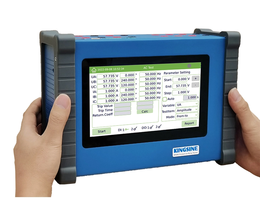
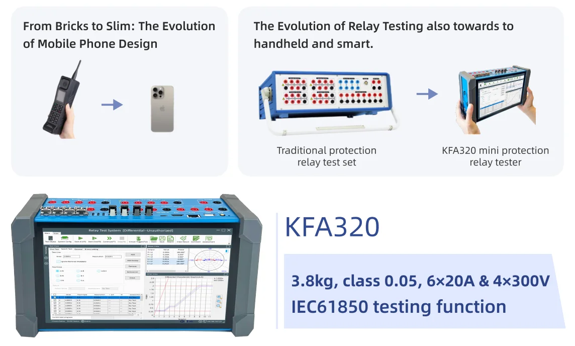
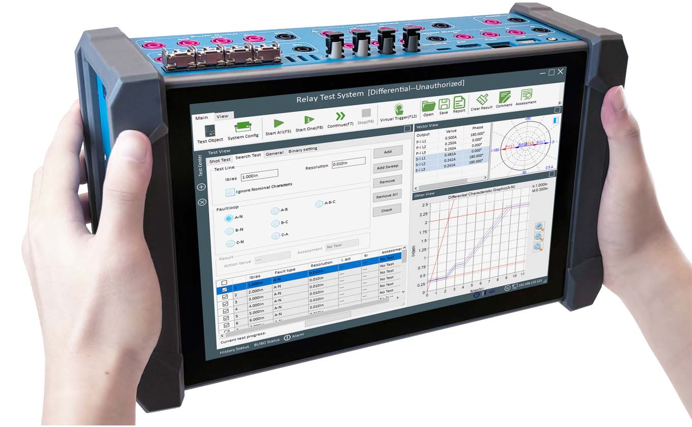
For engineers testing across multiple substations, weight is a direct productivity factor. Traditional desktop testers weigh 10–20 kg. Modern handheld units like the KINGSINE KFA320 weigh 3.8 kg and include a built-in touchscreen and rechargeable battery, eliminating the need for an external laptop during routine tests. When evaluating portability, consider not just weight but also setup and teardown time.
FAQs
What is secondary injection testing?
Secondary injection testing is a method where a test set injects simulated voltage and current signals directly into a protection relay’s secondary input terminals, bypassing the primary high-voltage circuit. It is the standard approach for routine relay testing because it is safe, portable, and does not require de-energizing primary equipment.
How often should protection relays be tested?
Most utilities test protection relays annually or biennially, depending on the relay type and grid code requirements. Electromechanical relays typically need more frequent testing due to mechanical wear, while numerical relays with self-monitoring can sometimes extend intervals. Always follow your organization’s protection maintenance philosophy.
Can one tester handle all relay types?
A general-purpose relay test set covers the most common protection types: overcurrent, distance, differential, directional, frequency, and recloser controls. Specialized functions like generator protection or transformer through-fault monitoring may require additional software modules or specific hardware configurations.
 English
  日本語
日本語  français
  Deutsch
  Español
  italiano
  русский
  português
  العربية
  Polska