Engineers specifying a protection relay tester face a common challenge: finding the right balance between capability and cost. Selecting an instrument with too few channels limits what your team can test in the field. On the other hand, buying excessive channels leads to idle hardware and wasted budget. The number of voltage and current output channels determines which protection schemes you can verify in a single session without tedious rewiring.
To make a smart investment, testing teams should look beyond immediate tasks. It helps to evaluate configurations from two perspectives: what you need to test today, and what you will need to verify as the power grid modernizes. This guide breaks down common channel configurations, from single-phase bench-testing units to advanced system-level sets.

1I+1V (Single-Phase): The Maintenance Workbench Essentials
Even in the era of digital substations, simple single-phase testers remain highly useful. They are the baseline for secondary injection testing.
During routine maintenance, field teams do not need to carry a heavy three-phase set just to test auxiliary, signal, or tripping relays. A lightweight, single-phase source is the fastest tool for verifying pickup and drop-out thresholds on individual voltage and current elements. It is also perfect for checking the operating limits of auxiliary coils. This makes it an essential, highly portable tool for distribution networks and simple control loops.
3I+3V (6 Channels): The Baseline for Distribution Protection
A six-channel tester—providing three current and three voltage outputs—is the entry point for three-phase secondary injection testing. This configuration simulates a standard three-phase power system under both normal operating conditions and basic fault states.
For standard overcurrent and directional overcurrent schemes, six channels are the industry standard. This setup allows engineers to verify three-phase overcurrent elements by injecting currents (typically 1A or 5A, separated by a 120-degree phase shift) while simulating voltage blocking conditions. It also handles basic impedance and distance testing on distribution feeders where you do not need secondary residual voltage compensation.
Testing teams use this configuration as their primary tool for preventative maintenance in medium-voltage distribution networks and industrial substations.
3I+4V (7 Channels): Integrating Synchronism Check and Zero-Sequence Compensation
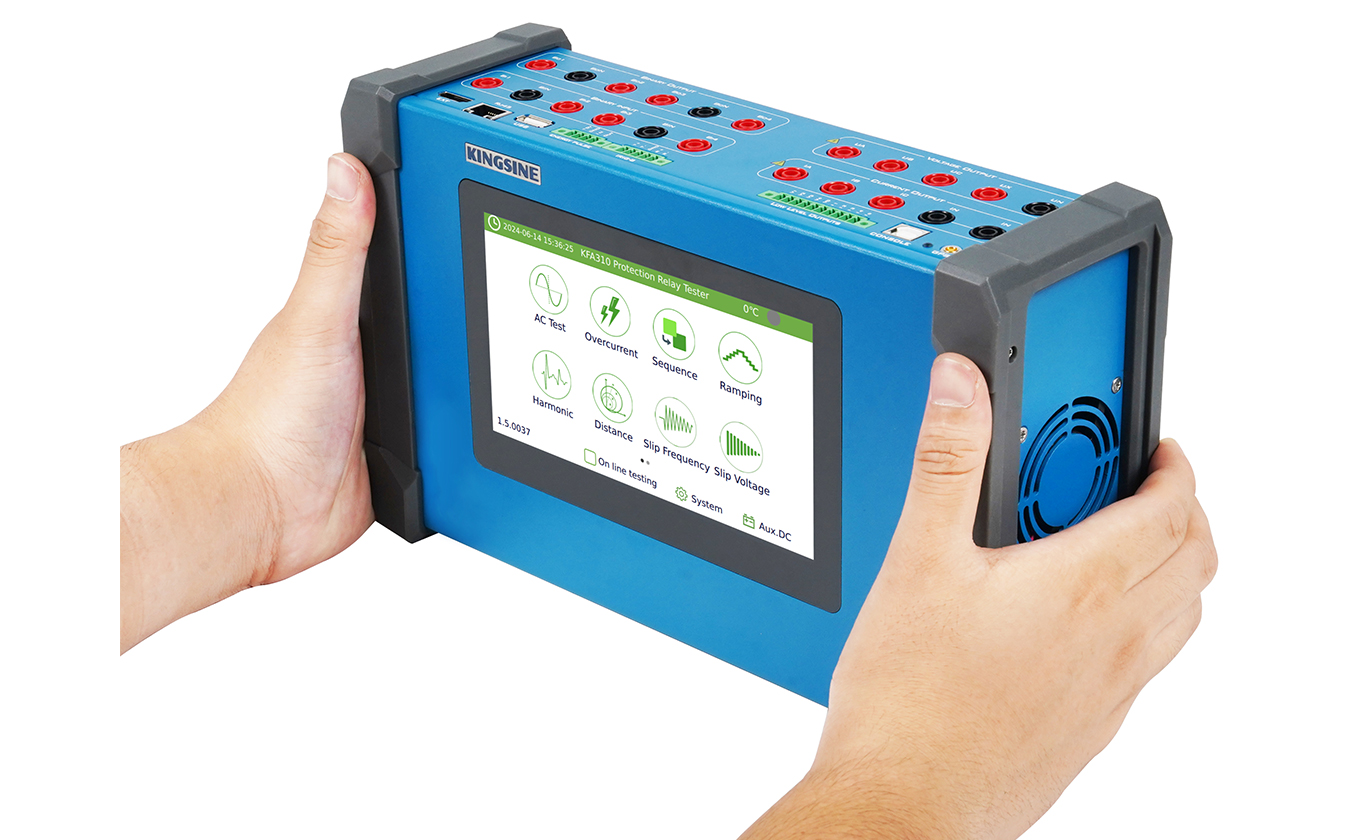
Adding a fourth voltage channel is one of the most cost-effective hardware upgrades in relay testing. It turns a standard six-channel unit into a flexible seven-channel tool. Portable instruments like the KINGSINE KFA310 are designed specifically around this configuration, packing versatile 4-voltage and 3-current outputs into a highly compact chassis to handle standard feeder and synchronization tests seamlessly in the field.
This extra voltage channel, often called Ux, serves several distinct technical purposes:
Synchronism-Check: Testing a synch-check relay requires simulating two independent power sources across a circuit breaker. The primary three voltage channels simulate the busbar side, while the fourth channel simulates the incoming line. This lets you adjust voltage magnitude, frequency, and phase angle to find the exact closing envelope of the relay.
Zero-Sequence Compensation: For ground distance and directional earth fault schemes, the fourth channel outputs the residual voltage. This serves as a polarization vector, ensuring the relay detects the fault direction accurately during ground faults.
Angle Boundaries: Directional power schemes often pair a line-to-line voltage with a phase current. A seven-channel tester provides the precise channel combinations needed to scan these sensitive boundaries.
6I+6V (12 Channels): The Standard for Dual-Source and High-Order Harmonics
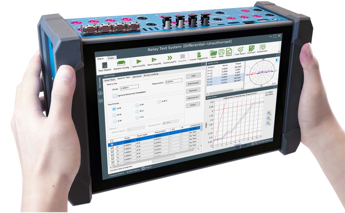
For differential protection, channel requirements increase significantly. Differential schemes compare the current vectors entering and leaving a protected zone to isolate internal faults from through-faults.
A standard two-winding transformer requires six current channels. A three-phase current source cannot simulate the currents on both windings at the same time. With a twelve-channel tester, engineers can inject three-phase currents into both the high-voltage and low-voltage windings simultaneously. This simultaneous output is necessary to map the percentage restraint curve, verify harmonic blocking, and measure trip times during internal faults.
Modern twelve-channel platforms also introduce advanced capabilities for field work:
Harmonic Superposition: High-end systems can superimpose high-order harmonics onto the fundamental wave. This is critical for testing the harmonic restraint of numerical relays, ensuring they do not trip falsely during transformer energization.
Fault Playback: Twelve independent channels let you reproduce transient and evolving faults using recording files from substation disturbance recorders. The hardware must maintain absolute phase and time alignment across all channels to recreate the actual event accurately.
Transfer Schemes: Automatic transfer systems often monitor two separate busbars. Six voltage channels allow you to simulate both busbar states at the same time, verifying the complex transfer logic and interlock sequences.
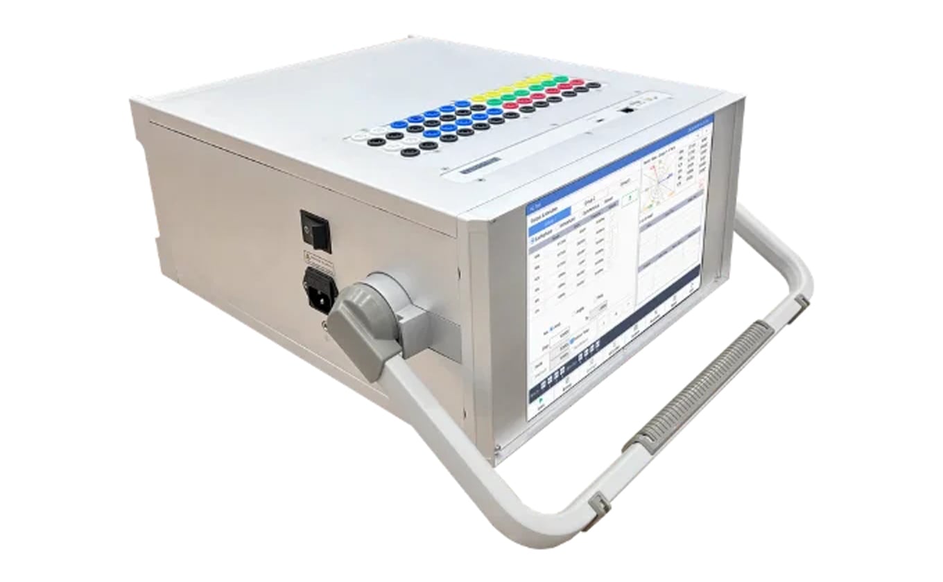
The KINGSINE KFA320 is one example that delivers 6 current outputs in a lightweight 3.8kg chassis, suitable for these dual-source differential test scenarios.
9I+9V (18 Channels): System-Level Multi-Terminal and Busbar Testing
In high-voltage and extra-high-voltage substations, multi-terminal lines and multi-winding transformers are common. For these systems, an eighteen-channel configuration (nine currents and nine voltages) is a technical necessity for complete system-level validation.
An eighteen-channel tester solves several complex field challenges:
Three-Winding Transformers: High, medium, and low voltage windings require three-phase current inputs on all three sides. An eighteen-channel tester allows you to sweep the entire differential boundary in a single test run. This eliminates manual rewiring and prevents human wiring errors.
Three-End Line Differential: Three-ended transmission lines require simultaneous current injection at all three terminals to simulate internal faults and CT saturation. A nine-current source handles this in a single setup.
Busbar Protection: Distributed busbar differential schemes sum current inputs from multiple physical feeders. An eighteen-channel set can simulate nine independent feeder currents simultaneously, allowing you to test the stability and logic of the entire bus protection zone.
Cross-Line Faults: Simulating a fault that crosses between two parallel lines requires six currents and six voltages. To simulate the surrounding healthy system at the same time, an eighteen-channel configuration is needed.
The KINGSINE K2099 is a portable 18-channel test set under 15kg that delivers configurable 9-phase voltage and current output, designed for these system-level scenarios.
Specialized Hardware Configurations
Beyond standard setups, specific field tasks require specialized channel layouts:
8-Phase Current Output: Designed for dual-circuit line differential systems where eight independent currents are needed to verify phase-blocking logic.
9V+4I Configuration: Optimized for complex bus transfer schemes. The nine voltage channels simulate three-phase voltages across three separate sections, while the four currents simulate feeder currents.
Cascaded Systems: For extreme coordination testing in converter stations or nuclear plants, standard devices can be cascaded. Connecting two eighteen-channel sets provides a synchronized 36-channel source for wide-area system testing.
Selecting the Right Channels for Your Projects
Selecting a relay test set is an investment in long-term field capability.
10-35kV Distribution: A six-channel or seven-channel tester (such as the KFA310 or KFA320) represents the ideal balance of portability (with lightweight micro-design down to 3.8kg) and core functionality.
110-220kV Transmission: A twelve-channel (6I+6V) test set (such as the KF86P) is the recommended standard. It provides the necessary outputs to handle the standard transformer and line differential schemes that form the backbone of regional grids.
500kV+ extra-high voltage and UHV projects: An eighteen-channel test set (such as the KINGSINE K2099) is the ultimate choice. In this environment, multi-side and system-level tests are mandatory. The K2099's 18-channel design enables "one-time wiring, comprehensive testing" for three-winding transformers and multi-terminal differential lines, reducing test setup time by up to 70% and completely eliminating risk points from repeated manual lead changes. For extreme scenarios, two K2099 units can be bridged to output up to 36 independent analog channels.
Mapping ANSI Protective Relays to Hardware Configurations
To help engineers select the appropriate hardware, the table below maps common protective functions under the IEEE/ANSI standards to the minimum channel requirements and corresponding KINGSINE hardware solutions:
| ANSI Device Type | ANSI No. | Channels Required | KINGSINE Test Sets |
|---|
| Distance protection relay | 21 | 3 | KFA320 / KF86P |
| Synchronising or synchronism-check relays | 25 | 4 or 6 | KFA320 / KF86P |
| Under-voltage relays | 27 | 3 | KFA310 / KFA320 / KF86P |
| Directional Power relays | 32 | 3 | KFA310 / KFA320 / KF86P |
| Undercurrent or under-power relays | 37 | 3 | KFA310 / KFA320 / KF86P |
| Negative sequence overcurrent relays | 46 | 3 | KFA310 / KFA320 / KF86P |
| Overcurrent/ground fault relays | 50 | 3 | KFA310 / KFA320 / KF86P |
| Inverse time overcurrent/ground fault relays | 51 | 3 | KFA310 / KFA320 / KF86P |
| Power factor relays | 55 | 3 | KFA310 / KFA320 / KF86P |
| Overvoltage relays | 59 | 3 | KFA310 / KFA320 / KF86P |
| Voltage or current balance relays | 60 | 3 | KFA310 / KFA320 / KF86P |
| Directional overcurrent relays | 67 | 3 | KFA310 / KFA320 / KF86P |
| Directional ground fault relays | 67N | 3 | KFA310 / KFA320 / KF86P |
| DC overcurrent relays | 76 | 3 | KFA310 / KFA320 / KF86P |
| Phase-angle measuring or out-of-step protection relays | 78 | 3 | KFA320 / KF86P |
| Automatic reclosing devices | 79 | 3 or 4 | KFA320 / KF86P |
| Frequency relays | 81 | 3 | KFA310 / KFA320 / KF86P |
| Motor overload protection relays | 86 | 3 | KFA320 / KF86P |
| Differential protection relays | 87 | 6 or 9 | KF86P / K2099 |
| Directional voltage relays | 91 | 3 | KFA310 / KFA320 / KF86P |
| Voltage and power directional relays | 92 | 3 | KFA310 / KFA320 / KF86P |
| Tripping relays | 94 | 3 | KFA320 / KF86P |
FAQs
How many current channels are needed for transformer differential testing?
A minimum of 6 current channels is required for two-winding transformer differential testing. For three-winding transformers, 9 current channels are necessary to simulate all sides simultaneously.
What is the purpose of the fourth voltage channel in a 7-channel test set?
The fourth voltage channel is primarily used for synchronism-check testing, providing an independent reference voltage to simulate the busbar or line side. It can also serve as a residual voltage output for grounding protection.
Can I test busbar protection with a 6-channel relay test set?
While basic elements can be tested, a 6-channel set cannot simulate the multiple feeders required for a complete busbar differential logic test. An 18-channel set is preferred for high-voltage busbar protection commissioning.


