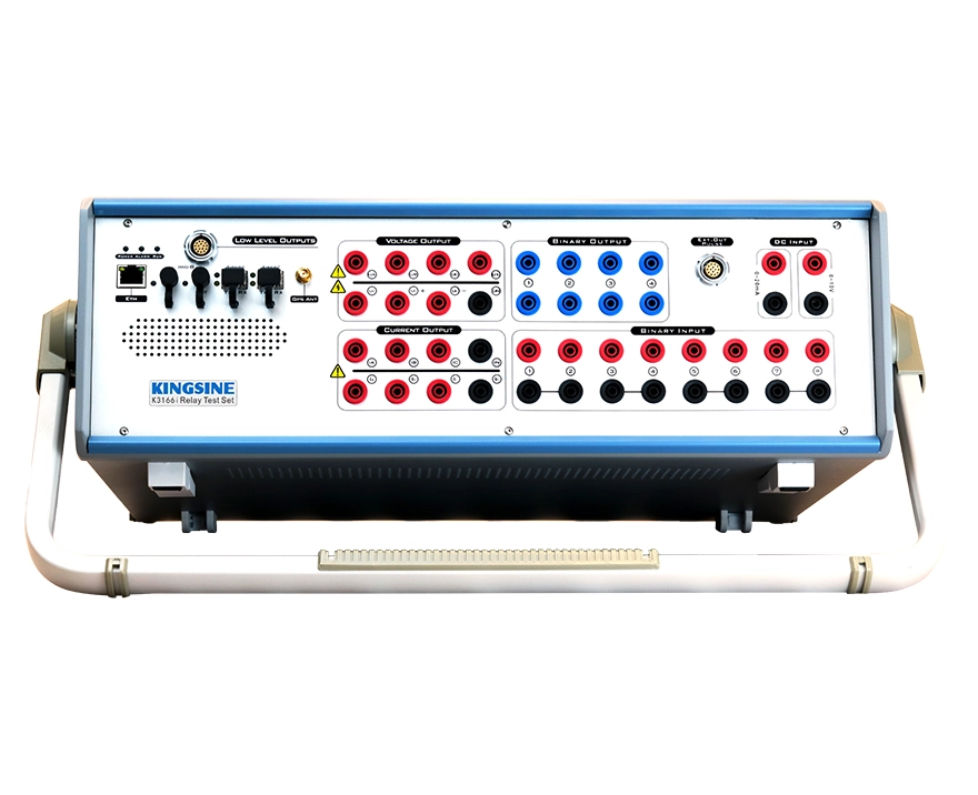
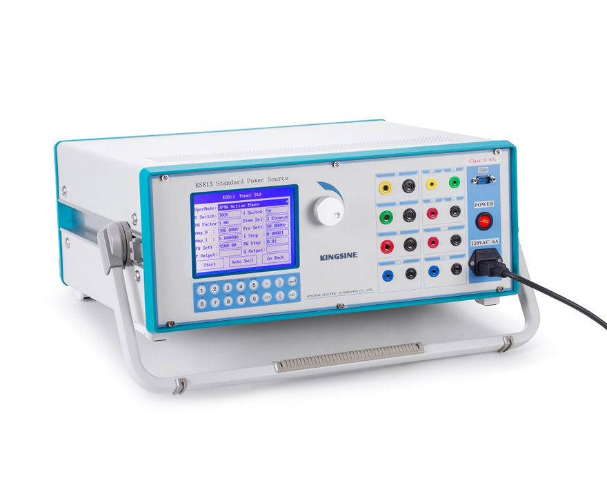
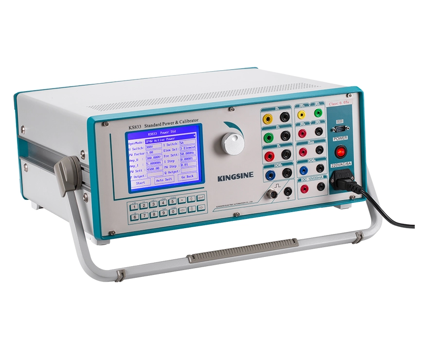
A data center's uptime depends on how quickly its protection system detects and isolates a fault. Every transformer, UPS, generator, and switchgear section relies on protection relays to trip the right breaker at the right time. This guide covers four common relay verification scenarios encountered during data center commissioning and maintenance.

Case 1: UPS Transfer Time Verification
A relay test set or programmable AC source simulates a mains failure by dropping the input voltage while a high-speed oscilloscope captures the output waveform. The interval between mains interruption and backup power establishment must be under 10 ms for online UPS systems per IEC 62040-3.
Before testing, confirm the UPS is under load and notify downstream IT operations. Connect the AC source to the UPS mains input and oscilloscope probes to the UPS output. Test at 100% load for the most representative results.
Configure the fault with normal voltage at 220V/380V and a trigger set to drop to 0V or below the undervoltage threshold for 100-500 ms. Activate the UPS static bypass so it remains in hot standby. Set the oscilloscope to falling-edge trigger at 90% of nominal voltage. Start the test and record T₀ (mains drops below threshold) and T₁ (output recovers to ±5% of nominal). Transfer time ΔT = T₁ - T₀. Repeat 3-5 times at no load, 50% load, and 100% load.
Transfer time should not exceed 10 ms. Voltage transient dip must stay within 10% of nominal and THD at the transfer instant should be below 5%. If transfer time exceeds 15 ms, server dropout or data corruption is possible.
Case 2: Distribution Transformer Overcurrent Protection Calibration
This procedure is the foundation for Cases 3 and 4. The test set injects controlled currents into the relay's CT secondary circuit to verify pickup value, reset ratio, and operating time against the protection setting sheet.
Confirm the relay is out of service, disconnect the trip output, and isolate CT circuits. Connect three-phase outputs (IA, IB, IC) to the relay current terminals with correct polarity. Select the overcurrent test module and verify the CT ratio matches the field setting. Read all stage settings (instantaneous, time-delayed, overcurrent) from the setting sheet.
Start with metering verification — apply known values and confirm the relay displays match. Then calibrate each stage separately. For pickup current, start at 90% of the setting and ramp slowly. Record Iop when the relay operates, repeat 2-3 times, and average. For the reset ratio, ramp current down after pickup and record Ire when the relay resets. Calculate K = Ire / Iop; the acceptable range is 0.85-0.95. For operating time, apply a fixed overcurrent at 1.2x or 2x the setting. The timer starts with injection and stops on relay contact closure. Compare the result to the setting sheet, for example 0.3 s ± 10%. If the relay uses inverse-time characteristics, test at 1.5x, 2x, 5x, and 10x and confirm against the specified curve.
Pickup current error should be within ±5% of the setting. Reset ratio must be 0.85-0.95. Definite time error should not exceed ±10% and inverse time must conform to the published curve. Metering deviation should stay within ±1%.
Case 3: MV/LV Switchgear Protection Cascade Coordination
Cascade testing verifies that upstream and downstream relays operate in the correct sequence — the nearest protection clears the fault first, with upstream acting as time-delayed backup. The test set injects fault signals at each protection location and monitors the operating sequence through multiple dry-contact input channels.
Verify the breaker truck is in the test position and the breaker is open. Confirm wiring matches the single-line diagram and disable external interlocks. Before cascade testing, calibrate each relay individually using the Case 2 procedure.
For a two-stage test (downstream feeder plus upstream transformer), connect the test set to the downstream feeder relay. Set the fault current to 1.2x the downstream Stage I setting. The test set monitors both relay contacts through two dry-contact channels. Record T_downstream and T_upstream. Coordination is correct when T_downstream is shorter than T_upstream with an interval of at least 0.1-0.2 s. If T_upstream equals or is shorter than T_downstream, the upstream breaker trips first and expands the outage zone.
For systems with three or more levels, such as incoming to bus-tie to feeder, test each level sequentially. If coordination fails, revise the protection settings and retest until the sequence is correct. The downstream relay must always operate before the upstream relay with the proper coordination interval.
Case 4: Diesel Generator Protection System Verification
The test set injects simulated faults into the generator relay's voltage and current circuits to validate overcurrent, reverse power, and ground fault protection elements.
Confirm the generator is shut down, disconnect the output breaker, and remove trip jumpers. Connect current outputs to CT input terminals, voltage outputs to PT input terminals, and trip contacts to the test set input channels. Read all settings from the setting sheet.
For overcurrent protection, follow the Case 2 procedure for phase-to-phase short circuit pickup and timing. For reverse power protection — which prevents the generator from motoring and damaging the prime mover — connect three-phase voltage and current from the test set. Apply forward real power first; the relay must not operate. Then adjust the phase angle so real power flows in reverse (negative power factor) and slowly increase toward the setting. Record the reverse power value at relay operation and verify the timing. For ground fault (zero-sequence) protection, connect single-phase current to the relay's zero-sequence input, note whether the setting specifies 3I₀ or I₀, and ramp slowly to pickup. Calculate the reset ratio using the same method as Case 2. Finally, run a close loop test simulating phase-to-phase shorts, abnormal system voltage, and single-phase grounds to confirm each protection output correctly drives the breaker.
Pickup errors for overcurrent, reverse power, and zero-sequence protection should all stay within ±5% of the setting. The reset ratio must be 0.85-0.95 and the correct breaker must trip with proper signal reporting.
Testing Tips and Equipment Shortlist
The facility cannot be taken offline, so testing must use redundant paths while the active path carries the load. Electrical rooms are space-constrained, making a portable six-phase test set under 4 kg a practical choice for moving between multiple rooms in a single shift. Documentation accuracy is critical — CT ratios, settings, and wiring should be verified against as-built drawings before any test. A mismatch between the coordination study and field settings is one of the most common issues found during commissioning.
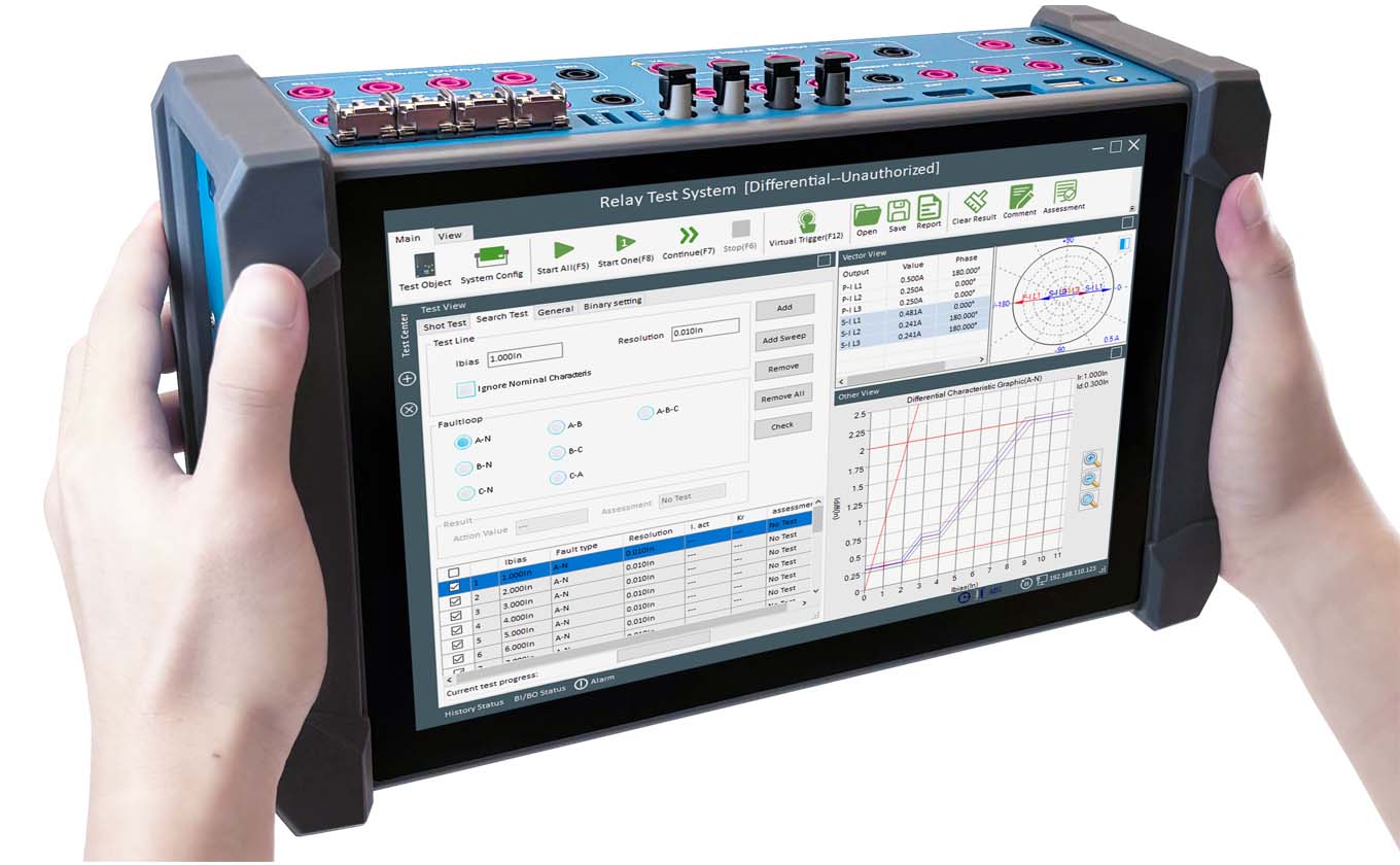
For equipment selection, key criteria include the number of phase outputs (three-phase for feeder relays, six-phase for differential and generator protection), output range, relay test library coverage for common brands (ABB, Siemens, Schneider, GE, SEL), configuration file import support (XRIO or RIO), and portability. KINGSINE KFA320 six-phase relay test set combines 0.05% output accuracy with a 500-plus relay template library in a 3.8 kg portable form factor suitable for data center environments with mixed relay inventories.
FAQs
What is the difference between secondary injection and primary injection?
Secondary injection applies test signals to the relay secondary terminals, verifying relay logic and timing without energizing the primary circuit. Primary injection tests the entire chain from CT primary through wiring to the relay, confirming CT ratio, polarity, and wiring integrity at actual fault current levels. Primary injection is recommended during initial commissioning and after any CT or wiring replacement.
Which protection relays are most critical in a data center?
The most critical relays are those protecting the UPS output, generator, main transformer differential, and feeder breakers. A failure in any of these can escalate to a facility-level outage. ANSI/NETA recommends annual testing for critical path relays in Tier III and Tier IV facilities.
Why is the reset ratio important in overcurrent protection testing?
The reset ratio (return coefficient) determines how much the fault current must drop before the relay resets after a trip. If the ratio is too low, the relay may fail to reset after a temporary fault, leaving the circuit de-energized unnecessarily. If it is too high, the relay may chatter near the pickup threshold. The accepted range is 0.85-0.95.
 English
  日本語
日本語  français
  Deutsch
  Español
  italiano
  русский
  português
  العربية
  Polska