Two relays, hundreds of kilometers apart, must detect the same fault at the same instant. That is the core challenge of line differential protection (87L) field testing. GPS-synchronized end-to-end testing is the best field practice that confirms both relays see the same fault at the same time, that the channel delay compensation is correct, and that the breaker trip times meet specification. For any utility or contractor commissioning a new 87L scheme, this test should be a mandatory step before line energization.

What Is Line Differential Protection (87L)?
Line differential protection, designated as ANSI code 87L, is based on a simple principle derived from Kirchhoff's current law. It compares the current entering a transmission line at one terminal with the current leaving at the opposite terminal.
Under normal load conditions or during an external fault (a fault outside the protected zone), the currents at both ends are equal in magnitude and opposite in phase. The vector sum — the differential current — stays near zero. When a fault occurs inside the protected zone, the currents become unbalanced and a measurable differential current appears.
87L can distinguish internal from external faults without impedance calculations or coordination curves, making it the preferred scheme for critical transmission lines.

How 87L Testing Differs from Other Relay Tests
Most relay tests — overcurrent, distance, or transformer differential — use a single test set at one panel. For 87L, a single-ended injection cannot verify how the two relays coordinate through the communication channel. The scheme depends on each relay comparing local measurements against the remote end's sampled values. If the channel delay compensation is wrong, or time references drift, the protection may misoperate — or worse, trip falsely during an external fault.
Why End-to-End Testing?
End-to-end testing is a field test method designed specifically to verify line differential protection schemes. Two relay test sets are placed at opposite ends of the transmission line and synchronized via GPS or BeiDou satellite timing. They inject a pre-calculated fault current sequence simultaneously into both relays.
The purpose is to validate the entire protection chain — CT circuits, relay differential algorithms with real remote data, channel delay compensation, and breaker trip timing at both ends. Without end-to-end testing, hidden issues like incorrect channel delay settings or GPS timing drift remain undetected until an actual fault occurs.
The Sync Foundation: ±10 Microseconds or Better
The reliability of an end-to-end test rests entirely on time synchronization. To simulate a real fault, both test sets must start their injection at the exact same moment. A timing error between the two units introduces a phase shift that can make an external fault look like an internal one, or mask a real internal fault.
Field-grade relay testers achieve this with built-in GNSS receivers that lock onto GPS and BeiDou (BDS) satellite constellations. Under typical substation conditions — even with the electromagnetic interference common in switchyards — the synchronization error should stay within ±10 microseconds. This level of precision ensures that when you simulate an external fault, the currents from both ends cross through zero together (through-going current), and when you simulate an internal fault, the difference current appears sharply and measurably.
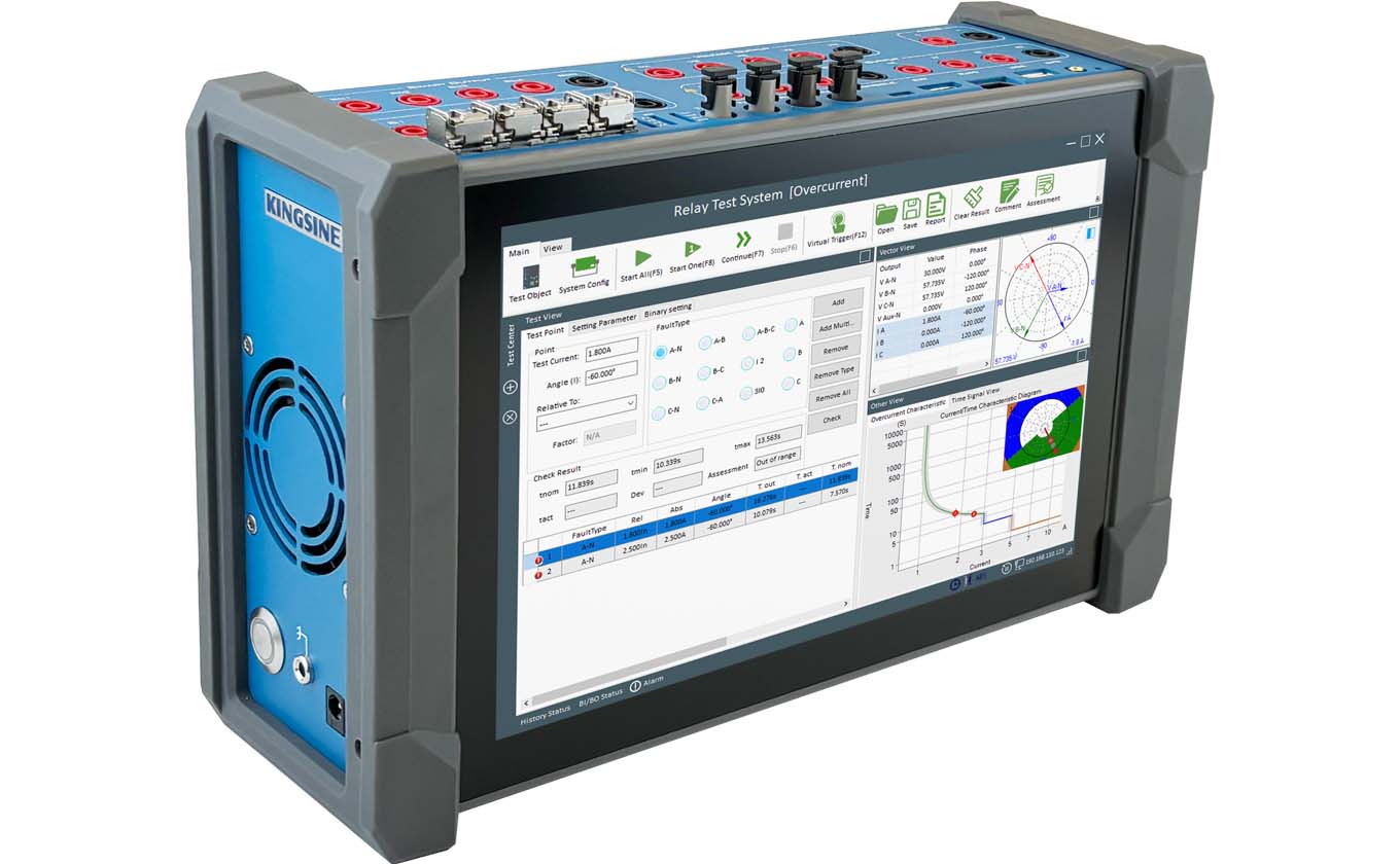
Field Setup: End-to-End Testing Procedure
Setting up an end-to-end test for line differential protection follows a consistent workflow. Below is the typical procedure used with KINGSINE relay testers.

Step 1 — Install GPS antennas at both ends with clear sky view. Connect to the GPS port on each relay tester.

Step 2 — Configure test parameters on the master-side tester: line length, CT ratio, relay type, and fault type (single-phase-to-ground, phase-to-phase, or three-phase).

Step 3 — Set GPS-synchronized trigger mode, program the start time, verify satellite lock (within ±10 µs), and execute the sequence. The remote unit fires automatically at the programmed instant.
Step 4 — Review the results. Check trip time symmetry, phase selectivity, and differential current profile on the superimposed oscillograph from both terminals. Repeat for in-zone and out-zone faults, then save the test reports.
4 Key Strengths of KINGSINE End-to-End Testing Solution
Based on field experience across dozens of line differential commissioning projects, KINGSINE relay testers are designed around four capabilities that directly address the pain points of 87L end-to-end testing.
1. Single-Operator Remote Synchronization
Traditional end-to-end testing requires two engineers on the phone, counting down to start the test simultaneously. This introduces human error and consumes valuable commissioning time.
KINGSINE testers solve this with preset GPS trigger scheduling. One engineer at the master station programs the start time (for example, 14:30:00.000000). The remote unit, also locked to the same GPS satellite constellation, starts automatically at that exact instant. This allows a single operator to run the entire test sequence — state simulation, fault waveform playback, and result recording — while the remote test set executes unattended at the other line terminal.
2. Built-In 87L Test Templates
Line differential testing involves multiple fault types (A-G, B-C, ABC, etc.) and zone logic discrimination (in-zone versus out-zone). Manually calculating injection parameters for each scenario is time-consuming and prone to error.
The KRT software suite powering KINGSINE testers includes dedicated 87L test modules. The engineer enters basic line parameters — line length, CT ratio, relay model — and the software generates the complete test sequence automatically. This includes pre-computed current vectors for both ends, correct timing for zone discrimination, and expected trip criteria. The template library covers mainstream relay models from ABB, Siemens, Schneider, GE, and SEL.
3. Direct Detection of Channel Delay Errors
One of the most common hidden defects in 87L schemes is incorrect channel delay compensation. The relay at each end must account for the propagation delay of the communication channel (typically fiber optic or pilot wire). If this compensation is off, the relay misaligns the remote current samples, creating a false differential current.
KINGSINE's end-to-end test exposes this immediately. When both test sets inject synchronized currents, any offset in the relay's trip time between the two ends points directly to a channel delay mismatch. This defect cannot be caught by single-ended injection methods.
4. Ruggedized Design for Unattended Remote Deployment
The remote substation terminal often lacks a control room. The test set may need to operate from an outdoor cabinet or a temporary shelter. KINGSINE testers are built for this environment:
Reinforced enclosures rated for industrial temperature ranges
Battery capacity sufficient for hours of synchronized operation, even without mains power at the remote end
High-brightness touchscreens readable in direct sunlight
Minimal external connections — GPS antenna input and test leads are all that is required at the remote site
Field Case: A 220kV Commissioning Project
There was a 220kV overhead line being re-commissioned after a protection upgrade. The new relays passed individual calibration at both ends. Pick-up accuracy, trip timing — everything checked out.
Then the commissioning engineer ran the end-to-end test, injecting an A-phase-to-ground fault. The oscillograph came back. Both relays started, but the remote-end trip pulse was late — 15 milliseconds behind the local side.
After a round of analyzing, the problem turned out to be a channel delay compensation parameter in the remote interface device. Someone had entered it wrong during a firmware update months earlier, and the single-ended tests never caught it.
The engineer corrected the value and ran the test again. This time the traces overlapped perfectly.
Without end-to-end testing, that 15-millisecond mismatch would have stayed hidden until the first real fault. By then, the answer would have been a blackout, and that's a risk no utility wants to take.
Frequently Asked Questions
What equipment is needed for end-to-end 87L testing?
Two relay test sets with built-in GNSS receivers, GPS antennas, and test leads. Both testers must support preset GPS trigger scheduling and capture synchronized oscillography from both line terminals.
What happens if the GPS signal is lost during the test?
Quality relay testers have a holdover capability — the internal oscillator maintains microsecond-level accuracy for several minutes after losing satellite lock, long enough to complete the fault sequence without interruption.
Are line differential schemes on fiber-optic channels also tested end-to-end?
Yes. In fact, fiber-based schemes require end-to-end testing even more urgently, because asymmetric channel delay compensation is harder to detect without synchronized injection at both terminals.


