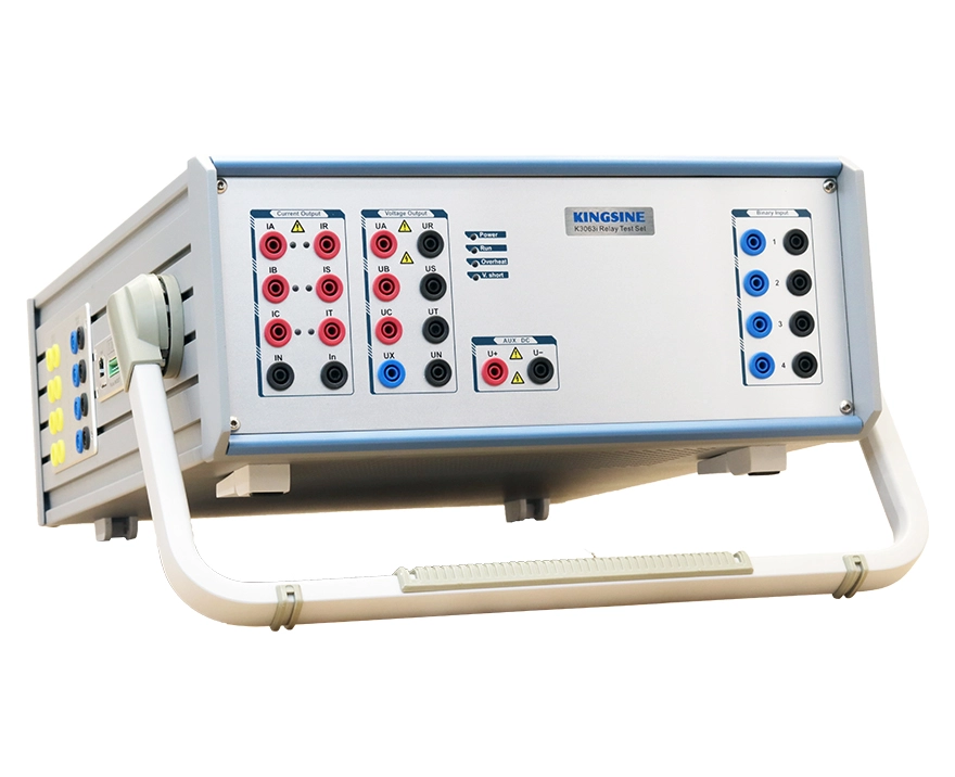
Commissioning a transformer differential protection at a 220 kV substation requires several steps: a percentage restraint characteristic scan, second-harmonic restraint verification, and a differential fast trip test. Each step demands sustained current injection — not a momentary pulse, but minutes of stable 5 A or 10 A per phase. If the test set thermally derates mid-scan, the curve is interrupted and the engineer must wait for the unit to cool before restarting. It is a recurring frustration with compact relay test sets that advertise high peak current but cannot sustain it.
The ability to deliver 10 A of continuous current across six channels in a 3.8 kg package is the result of deliberate engineering choices that prioritize thermal stability, electrical efficiency, and long-term reliability.
Three Engineering Decisions Behind Sustained 6×10A Output
Achieving sustained 6×10A output in a handheld enclosure required KINGSINE's engineering team to make three architecture-level decisions, each reflecting a quality-oriented design philosophy.

High-Efficiency Power Amplification
The power amplifier stage is the dominant heat source in any relay test set. For six channels delivering approximately 85 VA per phase at 10 A, total electrical output exceeds 500 VA. Amplifier efficiency determines how much of the input power becomes useful output versus waste heat.
Conventional linear amplifiers in many portable test sets operate at 50–70% efficiency. At 500 VA output, this means over 150 W of heat must be dissipated inside the enclosure. For a compact handheld chassis, managing 150 W of continuous heat without forced derating is extremely difficult.
The KFA320 uses a power amplifier design that exceeds 90% efficiency. At the same 500 VA output, waste heat drops to under 50 W — less than one-third of conventional designs. This margin is what makes sustained 6×10A thermally viable in a 3.8 kg package. The choice reflects a quality-first approach: rather than accepting thermal limits of conventional amplifier topologies, the team developed a high-efficiency architecture that prioritizes field reliability over design simplicity.
Streamlined PCB Architecture
The number of printed circuit boards directly affects both electrical efficiency and thermal behavior. Each additional board introduces power conversion losses, signal routing losses, and physical airflow obstruction.
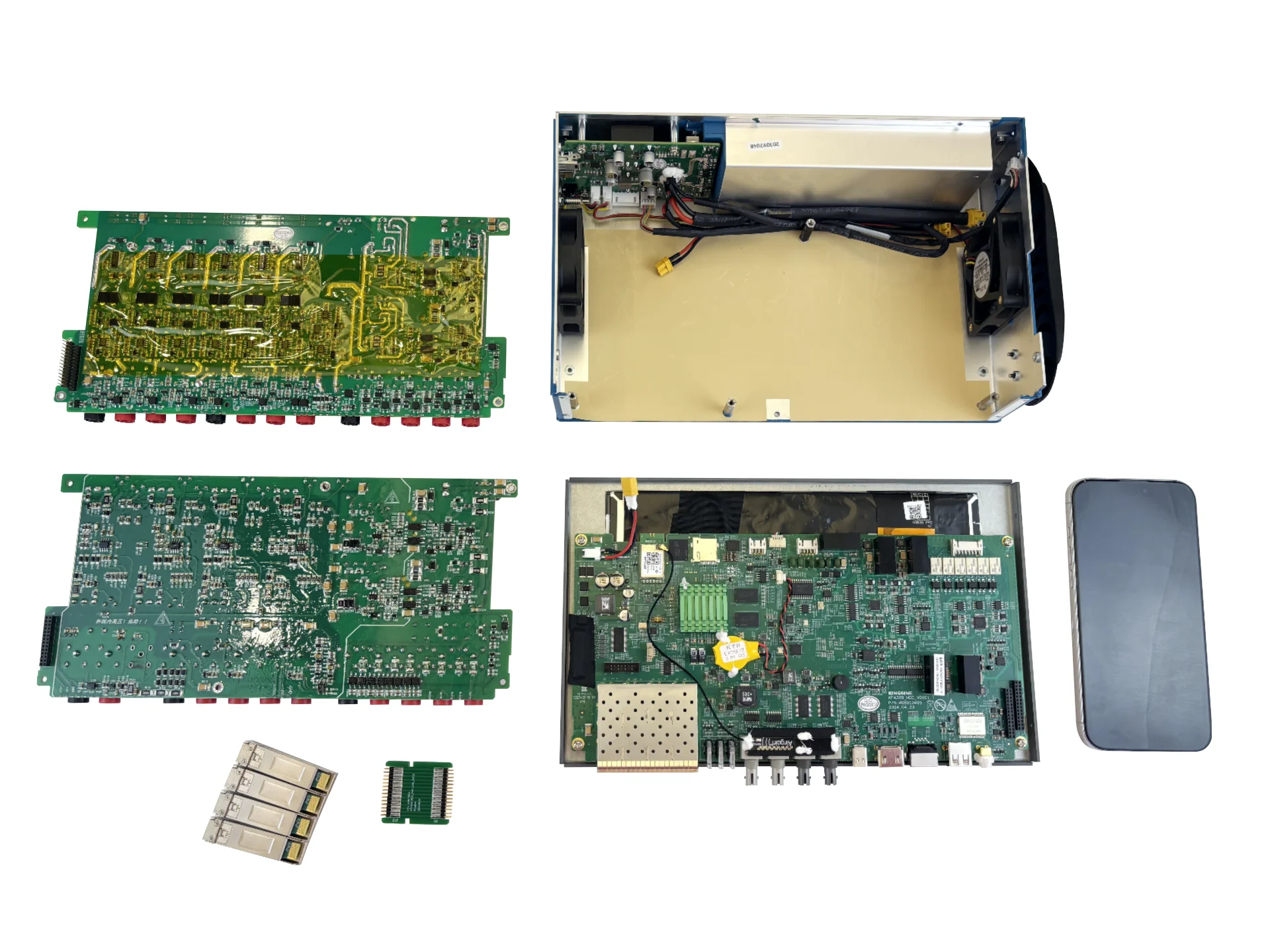
The KFA320 uses only four PCBs in total. This streamlined architecture reduces inter-board power loss and leaves more space for convective and forced airflow. In a sustained 6×10A test, the measurable result is that internal temperature stabilizes rather than rising continuously. Fewer boards also mean fewer connector interfaces that can degrade over time — a reliability consideration that matters for equipment expected to serve decades in field conditions.
Modular Construction for Lifecycle Quality
The same simplified architecture that benefits thermal performance also enables a modular, field-serviceable layout. Each amplifier stage is a replaceable module. If a channel fault occurs, the module can be swapped on site without returning the unit to the factory and without post-replacement calibration.
This design choice reflects a broader quality philosophy: a well-engineered test set should not only perform to specification but also stay in service with minimal downtime. In remote substations where returning equipment to a service center can take weeks, modular repairability is a practical quality differentiator that directly reduces operational cost.
What Sustained 6×10A Changes in the Field
A six-channel test set capable of sustained 10 A output traditionally weighs between 7 and 32 kg. The KFA320 weighs 3.8 kg — light enough for one person to carry to rooftop substations, offshore platforms, or confined underground chambers where every kilogram affects site logistics.
Beyond convenience, sustained output capability is a quality signal. A test set that maintains its rated current through a full differential curve scan without thermal intervention is a test set engineered for real-world conditions rather than spec-sheet benchmarks.
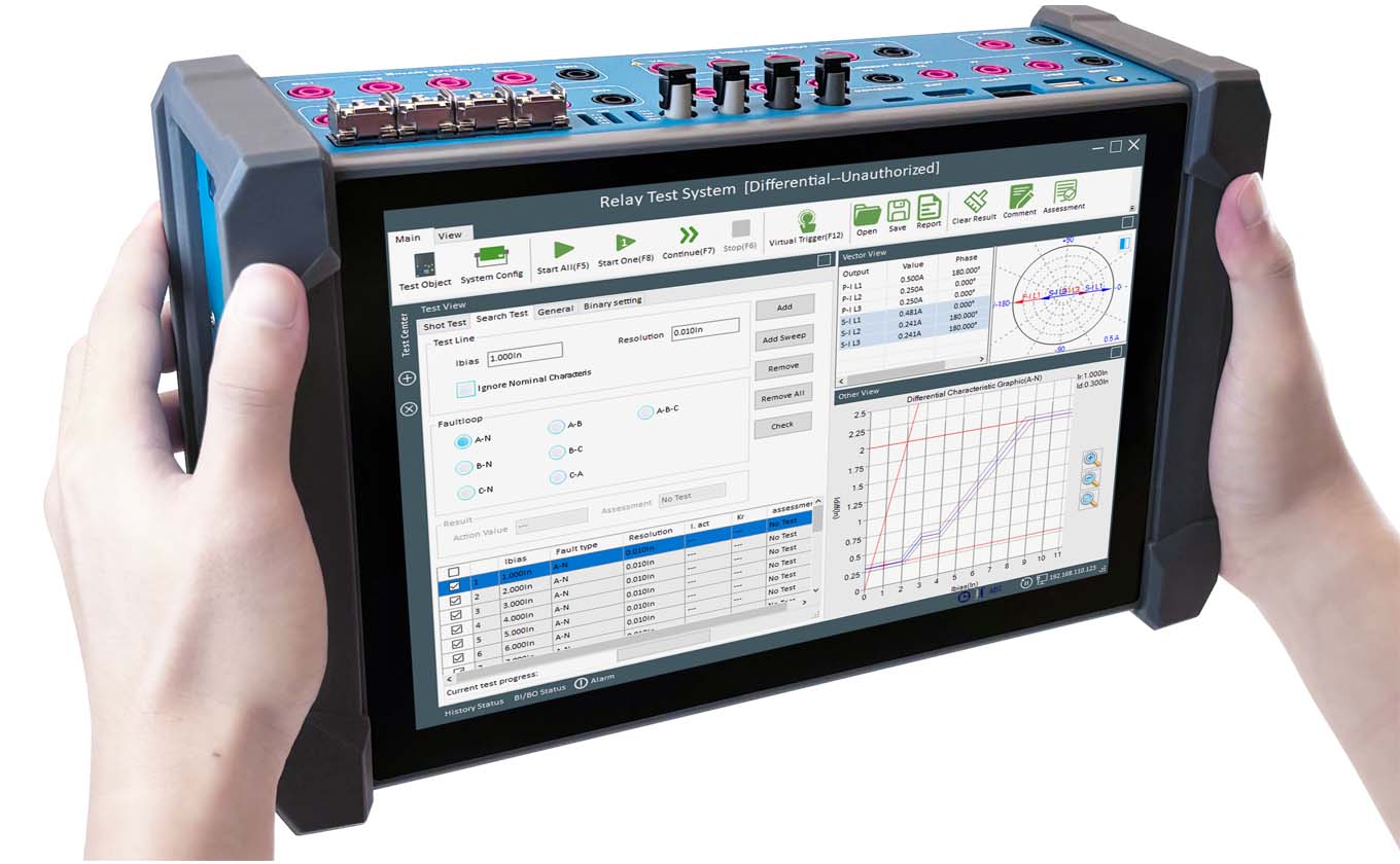
You can watch the live test video comparing the continuous output performance of the mini KFA320 versus a large traditional tester on YouTube.
FAQs
Does continuous 6×10A mean all channels must always output 10 A simultaneously?
No. The continuous rating simply guarantees that any load combination up to that limit is thermally sustainable. An engineer might use three channels at 10 A for a secondary circuit injection test, or six channels at lower currents for a differential test. The rating removes thermal uncertainty from test planning.
How does sustained output relate to test equipment quality?
Sustained output is a direct indicator of thermal design maturity. Addressing the heat management challenge correlates with broader design quality — efficient amplification, clean internal layout, and reliable component selection. For field engineers evaluating equipment, continuous-output rating is a more meaningful specification than peak current.
 English
  日本語
日本語  français
  Deutsch
  Español
  italiano
  русский
  português
  العربية
  Polska