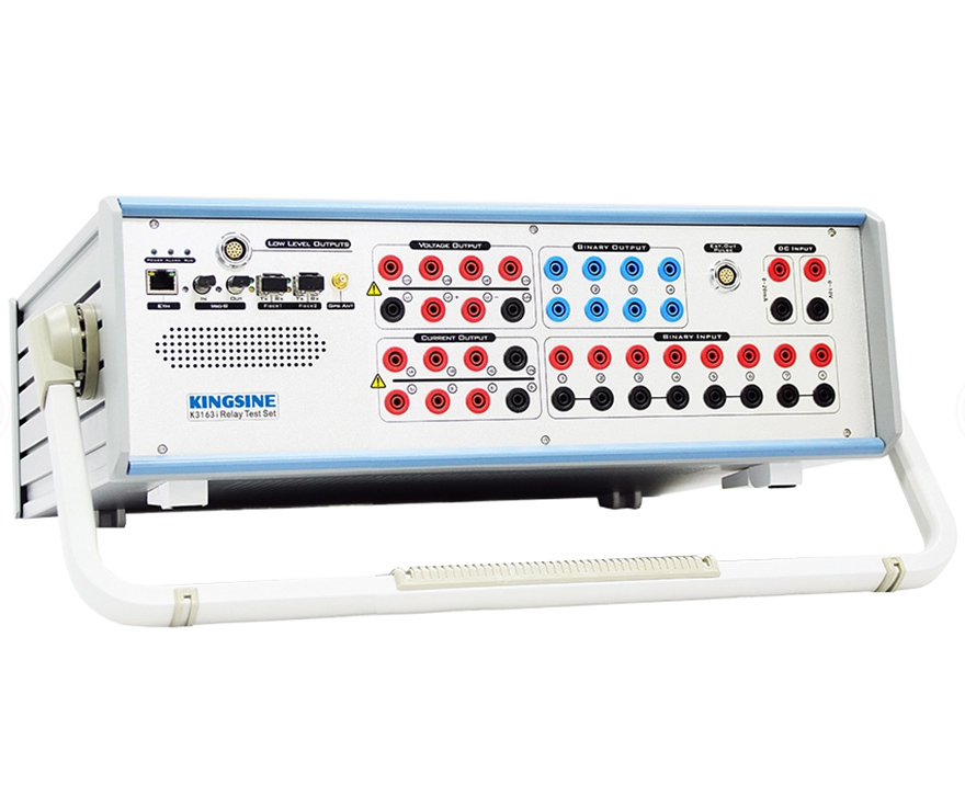
Item No.: 203112
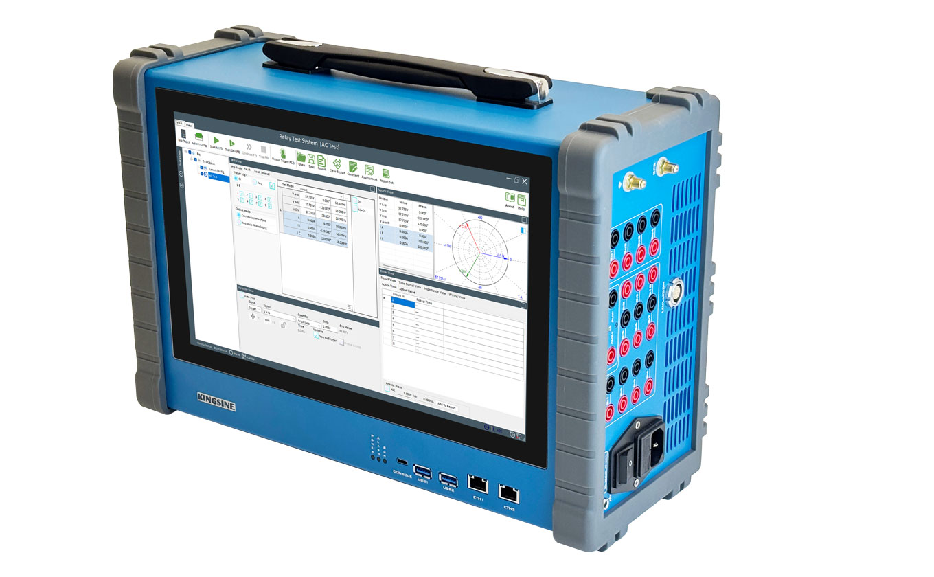
The world's lightest & high power secondary injection test kit for universal substation testing.
● 6x35A@425VA max & 6x310V@105VA max analog outputs.
● 10kg weight, easy carry on flight journey.
● Low-level signals output, energy meter testing, transducer calibration, and IEC61850 testing capability for optional.
If you want to know more about Kingsine substation testing equipment, please do not hesitate to contact us!
Basic Functions
The Kingsine KF86P universal relay test kit marks a multipurpose, light-weight, field portable secondary injection test kit. It is capable of testing a wide variety of electro-mechanical, solid state, and microprocessor based protective relays, motor overload relays, IEC61850 testing, and similar protective devices.
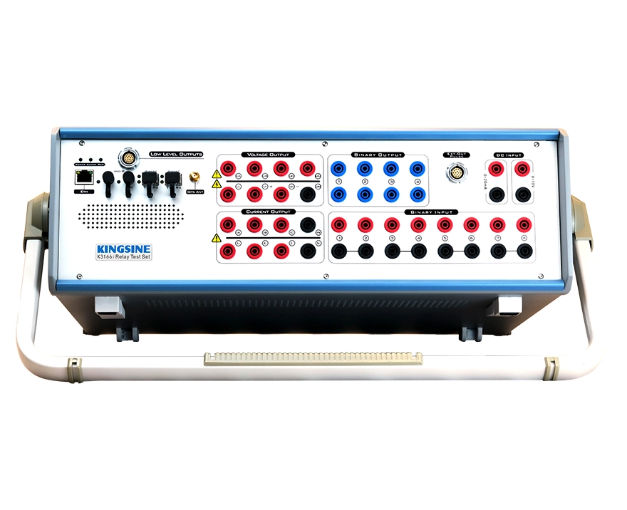
12 Analog Channels outputs, 6x35A & 6x310V, Each output channels are independent and simultaneous control of magnitude, Phase angle and frequency values, able to inject DC, AC sine wave and up to 60x harmonics.
Lightweight, <10kg, easy carry on flight journey
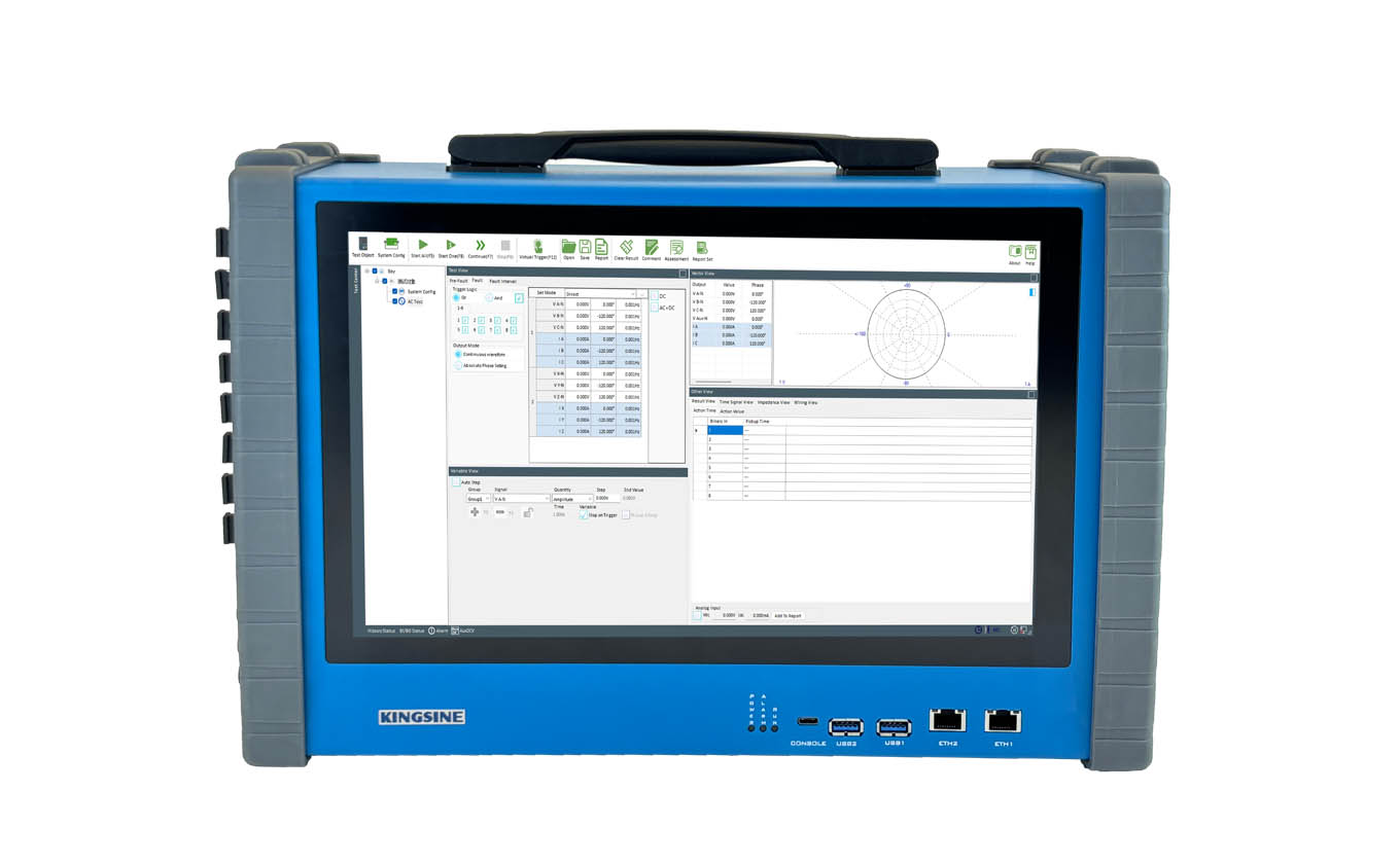
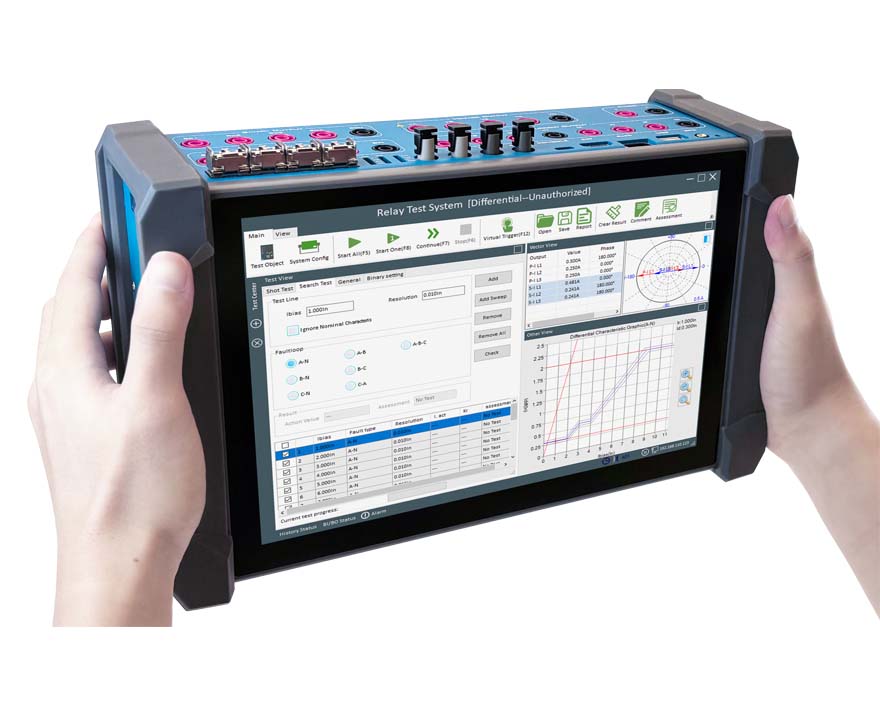
The unit can be operated either manually via built-in 13.3" touchscreen and keypad, or placed under full computer control via the KRT software, running on a PC.
Variable battery simulator, 24~350Vdc, 70Watts max output. Easily supply power for most protection devices.
Fully function KRT software for test management, graphical test modules, template organized, Xrio/Rio import/export, testing result review, auto result assessment and report generate, etc.
Transient play back up to 3KHz
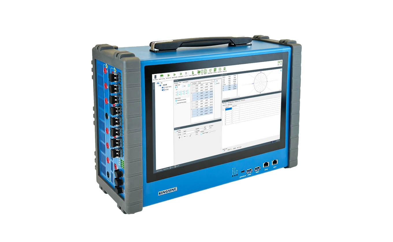
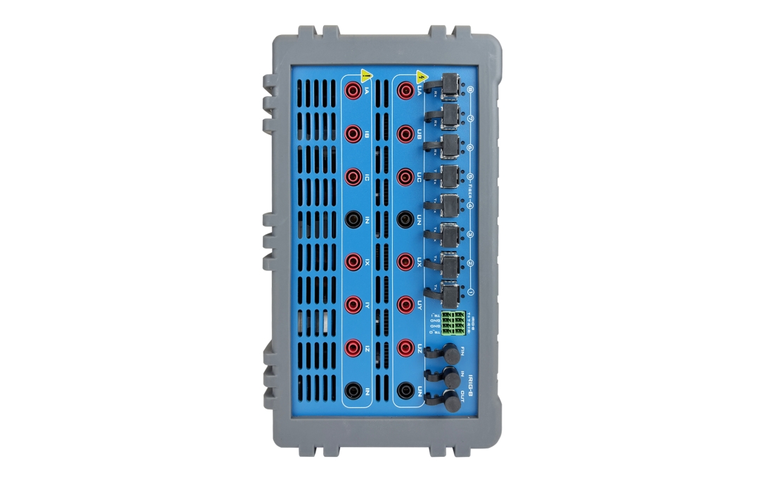
8x100/1000Mbit Fiber port for IEC61850 SMV and GOOSE simulations
Inbuilt GPS and IRIG-B synchronized end-to-end testing capability
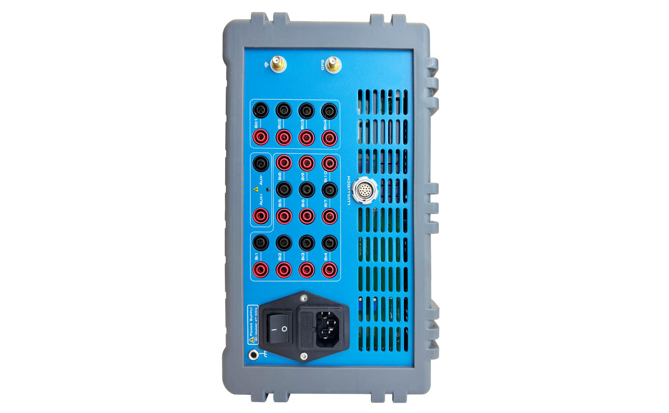
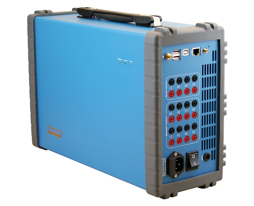
10 binary input, dry contacts or 0-300V potential contacts capability; 4 fast binary outputs isolated each and with <1ms response time.
Anti-clipping detect, Wrong wiring connect alarm and self-protect, overload and overheat protection
AC 85~265 / DC 127-350 power supply, World wide range power supply compatibility
3-Year free warranty and life-long maintenance
Free software upgrade
Learn more about the testing software designed for user-friendliness, multifunctional, and cost-effectiveness.
Advance Feature
Complied IEC61850 edition 1.0 & 2.0 standard
Transducer calibration
Energy meter calibration (Mechanical & Electronic meters)
10 Low-level analog outputs (8 Voltages + 2 Currents) up to 8V/20mA max.
Key Points
Innovative "Plug and Play" After-sales Service Advantages:
Simple structure, beginners can achieve independent installation.
Reduced after-sales costs.
Shortened after-sales time.
Goal: Complete after-sales within 20 working days.
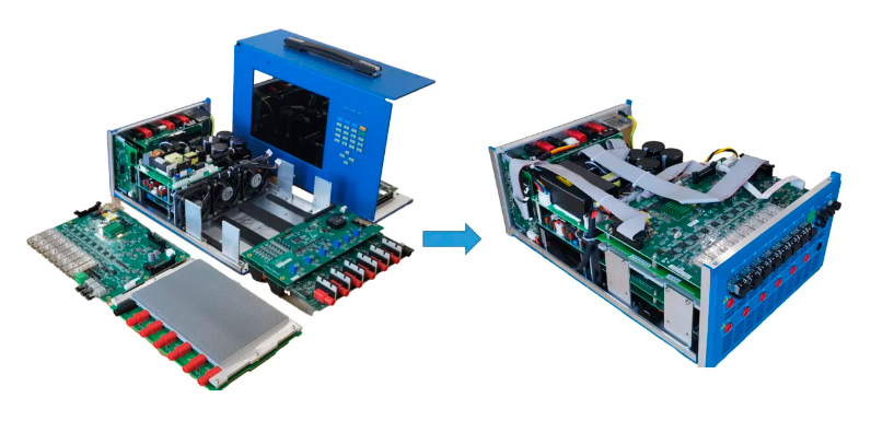
As a highly flexible solution for protection relay testing, the Kingsine KF86P universal relay test kit utilizes innovative technology, module design, and a simple internal structure, ensuring a higher level of product quality and providing assurance for a three-year warranty commitment. Besides, this secondary injection kit also contributes to achieving the quality objective of a 15-year product service life. For after-sales maintenance, only module replacement is required, and there is no need for accuracy calibration after module replacement. Once assembly is complete, it can be used directly, truly achieving "Plug and Play".
Public disclosure, the internal structure is visualized as shown in the following diagram:
| AC Current Source | |
| Amplitude & Power | 6×35A @ 424VA max each; 3×70A @ 670VA max each; |
| Accuracy | <0.015%Rd+0.005%Rg Typ. <0.04%Rd+0.01%Rg Guar. |
| Range | Range I: 3A Range II: 35A Automatic Range |
| DC Offset | <3mA Typ./ <10mA Guar |
| Resolution | 1mA |
| Distortion | <0.025%Typ. / <0.07% Guar. |
| Ascends/Descent response | <100us |
| DC Current Source | |
| Amplitude & Power | 3×20A @ 400W max |
| Accuracy | ±5mA @ <1A ±0.2% @ ≥1A |
| Ascends/Descent response | <100us |
| AC Voltage Source | |
| Amplitude & Power | 6×310V @ 105VA max each |
| Accuracy | <0.015%Rd+0.005%Rg Typ. <0.04%Rd+0.01%Rg Guar. |
| Range | Range I: 30V Range II: 310V Automatic Range |
| DC Offset | <10mV Typ./ <60mV Guar |
| Resolution | 1mV |
| Distortion | <0.015%Typ. / <0.05% Guar. |
| Ascends/Descent response | <100us |
| DC Voltage Source | |
| Amplitude & Power | 6×350V @ 100W max 3×700V @ 150W max |
| Accuracy | ±10mV @ <5V ±0.2% @ ≥5V |
| Ascends/Descent response | <100us |
| Frequency & Phase Angle | |
| Frequency Range | DC ~ 1000Hz, 3000Hz transient |
| Frequency Accuracy | ±0.5ppm |
| Frequency Resolution | 0.001Hz |
| Phase Range | -360°~360° |
| Phase Accuracy | <0.02° Typ. / <0.1° Guar. 50/60Hz |
| Phase Resolution | 0.001° |
| Auxiliary DC Supply (Battery Simulator) | |
| Range | 8 ~ 60Vdc (Max Load Current 1.16A) Accuracy<2% 60 ~ 120Vdc (Max Load Current 0.58A) Accuracy<1% 120 ~ 350Vdc (Max Load Current 0.2A) Accuracy<0.5% |
| Power | >69W max |
| Resolution | 10mV |
| Protection | Short-circuit protection |
| Overload Protection | Yes |
| Isolation | Isolated from other terminal |
| Binary Input | |
| Electrical isolation | 10 pairs of electrical isolated each |
| Input impedance | 5 kΩ…13kΩ(Empty contact) |
| Input feature | 0 V~300Vdc Or dry contact Binary 1-4 threshold can be set, binary 5-10 isolate every two pairs (Binary input turn over potential can be programmable) |
| Sampling Rate | 10kHz |
| Time resolution | 10us |
| Time measurement range | infinity |
| Time accuracy | ±1ms @ <1s ±0.1% @ ≥1s |
| Debounce time | 0~25ms (Software controlled) |
| Binary Output | |
| Quantity | 4 pairs |
| Type | Fast speed transistor, programmable software control |
| AC break capacity | Vmax: 250V(AC)/ Imax: 0.5A |
| DC break capacity | Vmax: 250V(DC)/ Imax: 0.5A |
| Electrical isolation | All pairs isolated |
| Time Synchronization | |
| Satellite synchronization | 1 × SMA, Use for GPS antenna interface Support GPS and Beidou Satellite |
| Fiber IRIG-B | 2 × ST, 1 for transmission, 1 for receiving |
| Electric IRIG-B | 1 × 6Pin 5.08mm phoenix terminal 1 for transmission, 1 for receiving |
| External trigger synchronization | 1 × 4Pin 5.08mm phoenix terminal external trigger input + external trigger output |
| Sync error | <1us |
| Communication Interface | |
| Ethernet | 2 × RJ45, 10/100M |
| WIFI | Inbuilt WIFI DHCP service |
| Serial port | 1 × RS232 |
| USB | 2 × USB2 |
| Weight & Size | |
| Size | 390mm×256mm×140mm |
| Weight | 10kg |
| Display | 13.3 inch LCD, touch screen |
| Power Supply | |
| Nominal voltage | 220V/110V (AC) |
| Allowable voltage | 85 - 265 VAC; 127V~350V(DC) |
| Nominal Frequency | 50Hz |
| Allowable Frequency | 47-63Hz |
| Current | 10A@220V, 16A@110V |
| Power Consumption | 1200VA max |
| Connection Type | Standard AC socket 60320 |
| Working Environment | |
| Operating temperature | -10~+55 ℃ |
| Relative humidity | 5~95%, Non-condensation |
| Storage temperature | -20℃ ~ +70℃ |
| Atmospheric pressure | 80kPa~110 kPa(altitude 2000m or lower) |
(Optional modules)
IEC61850 Functions:
Fully complying IEC61850 Sampling value and GOOSE; (IEC61850-9-1, IEC61850-9-2/(LE), IEC60044-7/8)
Able to simultaneously output sampling value and analog signals, or subscriber and publish GOOSE message and relay contact binary I/O function.
Up to 36 sampling value channels can be mapped.
| Fiber port (LC type) | |
| Type | 100Base-FX (100Mbit,Fiber, full duplex) |
| Port Number | 8 Pairs |
| Cable model | 62.5/125μm(Multiple-mode fiber, orange) |
| Wave length | 1310nm |
| Transmission distance | > 1Km |
| Status indication | SPD Green (lights): active connection Link\Act Yellow (blinking): data exchange |
10 Low-Level Channels Signal Output Function:
| Low-level signal output | |
| Output channels | 10 channels, 8 Voltage outputs + 2 Current outputs |
| Output port type | Phoenix terminal |
| Output range | 8x0~8Vrms; 2x0~20mA |
| Accuracy | (0.01~0.8 Vrms/0~2mA):<0.05% Typ. / <0.1% Guar. (0.8~8 Vrms/2~20mA): <0.02% Typ. / <0.05% Guar. |
| Resolution | 250µV |
| Harmonic(THD%) | < 0.05% Typ. / <0.1% Guar. |
| Frequency range | DC~1.0kHz, transient 3KHz |
| Frequency accuracy | 0.002%(Normal frequency) |
| Frequency resolution | 0.001Hz |
| Phase range | 0~359.9° |
| Phase accuracy | <0.02°,50/60Hz |
| Phase resolution | ±0.001° |
Transducer Calibration Function:
| DC Measurement Input | ||
| Voltage Input | Range | 0~±10V dc |
| Max Input | ±11V dc | |
| Accuracy | Accuracy <0.05% rg Typ. <0.02% rg Guar. | |
| Input Impedance | 1M ohm | |
| Current Input | Range | 0~±1mA / 1~±20mA, auto range |
| Max Input | 600mA | |
| Accuracy | <0.02% rg Typ. <0.05% rg Guar. | |
| Input Impedance | 15 ohm | |
Energy Meter Calibration Function:
| Energy Meter Calibration | |
| Sensor Usage | Mechanical meters / Electronic meters |
| Sensor Output | High lever:>4.5V, Low level:<0.2V |
| Pulse Input | 1 pulse input port, 5Vdc high level valid only. |
| Pulse Range | 500KHz pulse input Max. |
| Pulse Output | 1 Transistor output, Open-collector, 5Vdc/5mA |
The Lightest&High Power Universal Protection Relay Tester KF86P
Kingsine KF86P Secondary Injection Test Kit Introduction
KF86P Overcurrent Test
KF86P IEC61850 AC Test
KF86P Current Open-Circuit Protection
Portable, three-phase, programmable protective-relay test set, for steady-state, dynamic, transient, and fault-record playback testing of protective relays.
1. The equipment features a power supply of 85 - 265 VAC; 127V~350V(DC) at 47-63 Hz; a power cable is included, and the unit is equipped with a power-supply protection system.
2. It includes at least 3 variable voltage sources of 0 to 300 V AC rms minimum, with a minimum continuous power per channel in the range of 100 to 150 VA rms, and an accuracy of at least <0.015%Rd+0.005%Rg Typ. <0.04%Rd+0.01%Rg Guar..
3. It includes 6 (non-convertible) variable current sources rated at least 0 to 35 A AC rms continuous per channel, with a continuous power rating of at least 200 to 424 VA rms per channel; it also supports extension of the current-injection range with 3 variable current sources rated 35 to 70 A, with an accuracy of <0.015%Rd+0.005%Rg Typ.<0.04%Rd+0.01%Rg Guar..
4. The current sources are configurable such that the test set can inject at least one output of 120 A AC rms for at least 90 cycles (1.5 seconds) to perform high-level current-injection tests under high-burden conditions.
5. All sources (6 current and 3 voltage) are available simultaneously and are fully independent of one another in terms of phase angle, amplitude, and frequency.
6. It includes a protection system for the voltage and current sources (short circuit, open circuit, overload) that disables the corresponding output.
7. All voltage and current amplifiers support programmable phase angles over the range of -360° to +360°, with a minimum resolution of 0.001° and a maximum error of 0.01° at 60 Hz.
8. The equipment is capable of performing dynamic and transient simulations by playing back fault records in COMTRADE format.
9. It is capable of executing steady-state, dynamic, and transient-playback tests.
10. It is capable of simulating ramps (incremental and decremental) of the various variables (voltage, current, frequency, phase angle), as defined by the user via the software supplied with the equipment.
11. It includes an internal (integrated) DC auxiliary voltage source (battery simulator) that injects at least the selectable nominal range of 0 to 250 VDC and is built into the equipment. No external module is required.
12. It includes at least 4 digital outputs via integrated programmable dry contacts, with a minimum interrupting capability of 300 VDC, 8 A. No external module is required for this functionality.
13. It includes at least 10 programmable digital inputs for operation via dry contact or programmable voltage up to 250 VDC, integrated into the equipment. No external module is required for this functionality.
14. The equipment includes an antenna, a cable of at least 15 meters in length, and an internal receiver card or, alternatively, an external GPS satellite-clock module compatible with the test set, with a minimum accuracy of 1 microsecond, for performing synchronized point-to-point tests. For execution of these tests, the test system (equipment and software) allows the user to select the time at which the test will run by setting at least the hour, minute, and second, and also supports execution of the test via synchronizing pulses at constant intervals.
15. A CD or USB device is supplied per unit containing the most complete or advanced available version of the software (or equivalent), for the design, execution, and evaluation of protection-scheme tests, operating in Windows 10 and Windows 11 environments, that supports control and programming of the equipment for both manual and automated tests; the software is installable on an unlimited number of computers without being tied to a specific serial number of the test set.
16. For communication between the controller and the test set, Ethernet, USB, or wireless interfaces are supported; the communication cable between the equipment and the controller is supplied.
17. The software includes libraries of manufacturer-predesigned automated test routines that are user-adjustable without requiring programming, enabling automatic sequential testing of the operating characteristics of distance relays, non-directional and directional overcurrent relays, current-differential relays with percentage characteristic and harmonic restraint, voltage relays, directional power relays, and voltage-supervised overcurrent relays, all in single-phase, two-phase, and three-phase modes, as well as synchronism-check relays, frequency relays, Volts/Hz relays, and out-of-step/loss-of-synchronism relays.
18. The automatic test routine is adaptable or editable by the user to test operating-characteristic points even when the protective-relay settings are changed. This feature is available in the software.
19. The software is capable of loading relay settings obtained from text-format files (XML, CSV, RIO, TXT, etc.).
20. The software is capable of modeling state sequences to determine operating times and logical timing sequences. It supports chaining multiple states via a logical transition condition. It supports definition of time-measurement conditions to verify correct relay operation, in addition to tolerances for each measurement condition. The module includes oscillography to display current, voltage, and binary-input signals to facilitate analysis of the relay under test.
21. It includes a ramp generator capable of simultaneously sweeping both the magnitude and the frequency of the voltage (i.e., two ramps). In addition to continuous sweeps, the software is capable of generating sweep ramps in incremental and decremental pulses.
22. The operating characteristics of overcurrent, distance, and differential (restraint and harmonic) relays are displayed on the test plane along with tolerance (error) bands. During testing, results are plotted on the operating characteristic to facilitate comparison between the theoretical and actual curves, in order to visualize any misalignment of the actual curve.
23. The software includes a dedicated overcurrent module with the capability to test directional and non-directional relays with automatic evaluation of the trip-time characteristic, the directional limits of the overcurrent elements, and the pick-up/drop-out ratio. It tests phase, ground, positive-sequence, negative-sequence, and zero-sequence elements. For each element, the trip characteristic is individually selectable and displayed on the I/t diagram and on a directional diagram.
24. The software is capable of overlaying the characteristics of each element on the I/t diagram and on the directional diagram. For each test trip it performs an evaluation of relay operation based on the allowable tolerances for current measurement and operating time. The module for performing this test includes oscillography to display current, voltage, and binary-input signals to facilitate analysis of relay operation during the test.
25. It includes a distance-function test module with a search method for the reach zones. It supports definition of test points relative to: the reach zone, line length, and line angle. The distance module includes simulation modes for constant current, constant voltage, and constant source impedance. The test software is capable of operating in primary or secondary impedance values, with the possibility of switching between these modes at any time before or after the test.
26. The software supports testing of differential protection schemes (transformer, generator, busbar) for 100% of their operating characteristics. Tests can be performed with single-phase, two-phase, and three-phase faults. An operating-characteristic search function is incorporated.
27. The operating characteristic of the differential protection (trip and restraint) is displayed on the test plane along with tolerance (error) bands. During testing, results are plotted on the operating characteristic to facilitate comparison between the theoretical and actual curves.
28. For testing of the harmonic-restraint characteristic (2nd and 5th harmonics), the software displays the entire operating characteristic along with the tolerance band.
29. The software includes a dedicated test module for synchronism-check relays that allows test points to be plotted on the relay’s operating characteristic.
30. It includes software that supports testing of protective relays in accordance with the IEC 61850 standard.
31. The equipment is capable of testing relays in accordance with the IEC 61850 standard with the following features:
1) Ability to easily subscribe to GOOSE/GSSE, DATA REPORT, and MMS messages sent by the relay and use them to determine response time.(Optional)
2) Capability to publish GOOSE, DATA REPORT, and MMS messages including the state of the test set outputs, for simulation of the circuit breaker and other devices.(Optional)
3) Capability to capture GOOSE messages on the network and identify a particular message upon a state change in the GOOSE message; this applies equally to DATA REPORT and MMS messages.(Optional)
4) Capability to import SCD files as well as CID files, with tools for comparing said SCD and CID files against the actual network capture and displaying the differences found.(Optional)
5) Provision of GOOSE message search (filter) tools based on the following criteria: IED NAME, LN NAME, IED IP, IED MAC ADDRESS, VLAN ID, etc.(Optional)
6) A communication interface for monitoring state changes of the selected signals required for all protection-scheme tests, discriminating the logical nodes on which the signals reside, and time-stamping the state change of the signals.
32. The software is capable of playing back fault files captured by relays, disturbance recorders, or designed with transient-simulation software, in COMTRADE format. Basic editing of the fault file, such as extending the pre-fault or fault interval, is supported.
33. The equipment supports synchronized end-to-end tests with a GPS unit with integrated antenna that supports the PTP time protocol in accordance with IEEE 1588-2008 / IEEE C37.238-2011. The software allows selection of the time at which the test will run by setting at least the hour, minute, and second, and also supports execution of the test via synchronizing pulses at constant intervals.
34. Reports are exportable to MS Word or similar word-processing programs. The software supports inclusion of graphs showing the characteristic curves and test results.
35. The software includes functionality to plot and view COMTRADE-format files for event analysis.
36. The software is capable of importing relay configuration files in “RIO” or “XRIO” format for evaluation and testing.
37. All software features described above are included in the license provided with each test set and available for unrestricted use by the user.
38. The equipment includes 24 test leads with a minimum length of 2 meters for connections from the equipment to the relay for all voltage outputs, current outputs, and digital inputs and outputs.
39. Banana-plug connection accessories are included for each test lead.
40. Communication cables are included for controller–equipment–test-modules and controller–printer connections, along with all cables necessary for operation of the equipment.
41. The equipment weighs in the range of 9 to 10 kg, excluding the weight of cables, transport case, and peripheral accessories, to facilitate easy transport.
42. Software is included for configuring and adjusting all functions of the equipment, as well as for downloading data and generating test-result reports in Excel format, with its respective original licenses and perpetual usage rights. This software supports creation of a database, test history, and automatic reports containing graphs and test values.
43. A sealed, heavy-duty transport case with a handle and wheels for rolling is included.
44. The test set is a current-production model; that is, it is not a discontinued model.
45. The operation and maintenance manual for the equipment and software is included, along with 1 set of communication cables for controller–equipment–test-modules and controller–printer connections, and all cables necessary for operation of the equipment. Manuals may be delivered in digital form on a USB device.