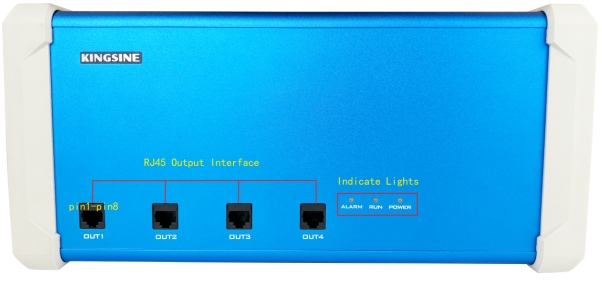
KINGSINE LPIT Adapter is a high-precision signal conversion and amplification device specifically designed for Low Power Instrument Transformer (LPIT) testing. Compatible with protection relay testers, our LPIT Adapter supports multiple signal input types and amplified output, meeting the IEC61869 standard interface requirements. It is an ideal tool for testing smart protection devices in power systems.

Core Advantages:
1. High-Precision Signal Processing
Input accuracy up to 0.05%, output range 0~35 Vrms (differential 70V), ensuring reliable test data.
Compatible with LPIT protection relay devices from leading brands such as ABB and Siemens.
2. Versatile Interface Compatibility
Multi-functional input interface compatible with various products
Standard RJ45 output interface with plug-and-play functionality, fully compliant with IEC61869 interface standards
3. Intelligent Signal Simulation
Signal amplification capability: 0~8 Vrms input to 0~35 Vrms output
Differential output: Up to 70 Vrms maximum output, meeting high dynamic range testing requirements
4. Transformer Signal Simulation Capability
Capable of simulating low-level output characteristics of ABB KEVA 17.5 B20 (voltage transformer/VT) and KECA 80 C104 (current transformer/CT) for testing LPIT-compatible protection relay testing equipment.
Number of Channels: 8
Output Range: 0~8 Vac/dc
Accuracy:
(0.01~0.8 Vrms): <0.05% Typ. / <0.1% Guar.
(0.8~8 Vrms): <0.02% Typ. / <0.05% Guar.
1. Wiring Configuration
(1) Connect KINGSINE KFA310 to the LPIT Adapter using the dedicated adapter cable.
(2) Interface the LPIT Adapter with the ABB protection device via RJ45 port, connecting to the ESSILEEC test terminal module.
(3) Ensure correct wiring of current channels (S1/S2) and voltage channels (a/N)

2. Software Configuration
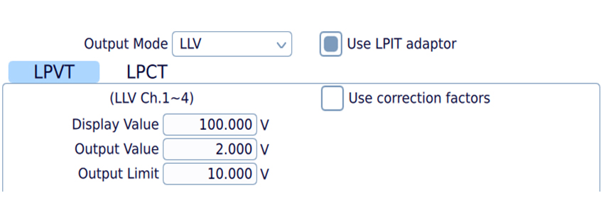
(1) Access the KFA310 system setting module and select Low-Level Output (LLO) Mode
(2) Configure LPIT Parameters:
LPVT (Low-Power Voltage Transformer): Set the input/output ratio according to the transformer's actual ratio (e.g., for a ratio of 10000, with primary voltage of 50kV, set the Display Value to 50000V and Output Value to 5V).

LPCT (Low-Power Current Transformer): Set the current signal input/output ratio according to the transformer specifications (e.g., for a transformer with primary current of 200A@50Hz and RSV=0.15mV/Hz, set the Display Value to 200A and Output Value to 0.15×50×1000 = 7.5V )

3. Functional Test Example: Overcurrent Protection Test
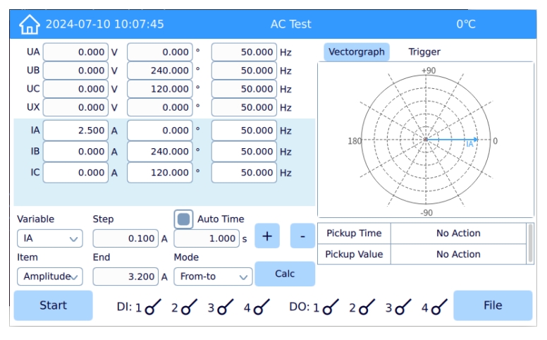
(1) In the KFA310 AC module, configure the test voltage and current values.
(2) Inject LPCT simulated signals, gradually increasing amplitude until reaching protection trip threshold.
(3) Monitor REX615 protection device response, recording trip time and accuracy
(4) Compare measured values with setpoints to validate protection logic correctness.
