The operating logic of distance protection essentially hinges on a comparison between the fault impedance and the set value—if the fault impedance is less than the set value, the protection operates; otherwise, it does not. The accuracy (e.g., impedance, operating time), adaptability (e.g., compensation factors for complex lines), and compliance (e.g., error tolerance) of these settings directly determine whether the protection can act correctly in critical situations.
However, traditional testing tools face three major challenges:
Difficult parameter matching: Site-specific parameters (e.g., PT/CT wiring, ground compensation factor, zero-sequence compensation factor) must be manually converted before input, which is error-prone.
Slow setting verification: Each protection zone (Zone 1/2/3) must be tested individually, consuming significant time.
Abstract characteristic analysis: Protection operation boundaries are not intuitively displayed, making it difficult to assess the appropriateness of settings.
The KINGSINE KRT Distance Protection Module addresses these issues with a solution focused on precise setting verification and intuitive custom curves, achieving complete parameter matching, full-range setting coverage, and visualized characteristics analysis.
1. One-Click System Parameter Matching: Reproducing Real-World Conditions 1:1
The "System Parameters" section of the distance module maps directly to key field values:
Line Parameters: Supports direct input of line length (e.g., 75.000 km) and impedance angle (e.g., 75.000°). The impedance is automatically calculated (Z = ρ×L/S + jωL×L), eliminating manual errors.
PT/CT Configuration: Choose PT wiring (line side/bus side) and CT polarity (toward line/toward bus), fully aligning with on-site secondary circuits.
Compensation Coefficients: Custom settings for distance compensation (KL) and zero-sequence compensation (KM), including coefficient (e.g., KL=0.667, KM=0.667) and angle (e.g., 0.000°), to mitigate impedance measurement deviation on long or cable lines.
Whether dealing with overhead, cable, or hybrid lines, site parameters can be imported in one click to ensure full test-environment fidelity.
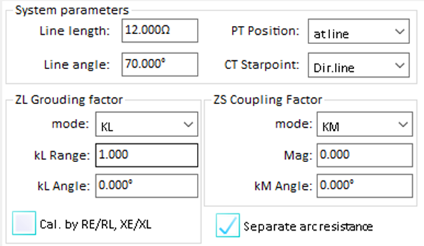
2. Batch Management of Protection Zones: Doubling Setting Verification Efficiency
Protection Zones I/II/III are the focus of distance setting verification. The "Protection Zone" feature supports importing, creating, editing, and deleting multiple zones:
Create Zones: Define usage area (e.g., z1), label (e.g., Zone I), type (e.g., trip), fault type (e.g., single-phase A-N ground fault), and operating time (e.g., 50.000 ms).
Batch Verification: Select multiple zones (e.g., Zones I & II); the module automatically outputs test signals in sequence, monitors each zone's operating impedance (|Z|) and time (t), and logs the results.
Import/Export: Load protection zone settings from KRT files (e.g., design institute setting sheets); export results in XML/PDF to instantly generate verification reports.
Compared to traditional methods that may take an hour to verify three protection zones, the KINGSINE module can complete the task in 15 minutes—a 75% efficiency gain.
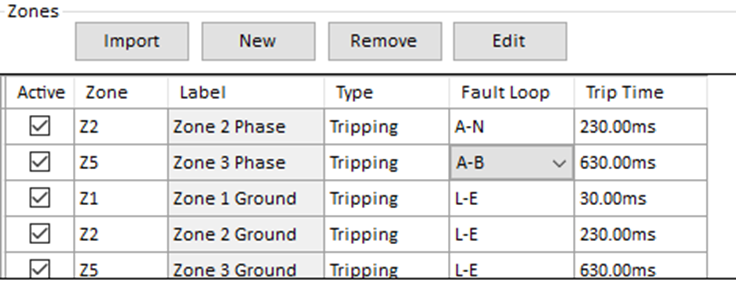
3. Fine-Grained Error Settings: Full Standards Compliance, Zero Risk
Distance protection settings must comply with standards such as IEC 60255-151 and DL/T 995-2016. The KINGSINE distance module allows flexible error configuration:
Time Error: Define relative time error (e.g., ±5.000%) and absolute time error (e.g., +100.000 ms / -0.000 ms).
Impedance Error: Set relative (e.g., ±5.000%) or absolute impedance error (e.g., +0.000 Ω / -0.000 Ω).
Auto Assessment: Any test result outside the defined range is automatically flagged as "Fail," with anomalies highlighted (e.g., time deviation of 120 ms).
Engineers no longer need to manually calculate errors—compliance can be quickly verified, reducing risks of misoperation.

4. Intuitive Custom Curves. Clear and Controllable Characteristic Boundaries
The Custom Curve feature converts abstract numeric settings into graphical boundary visualizations using a template + real-time sync design for intuitive analysis.
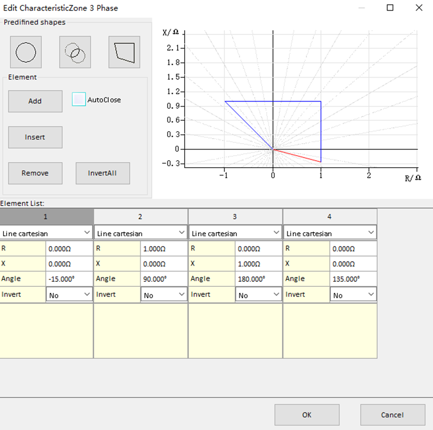
(1) Predefined Templates: One-click matching of common characteristic shapes
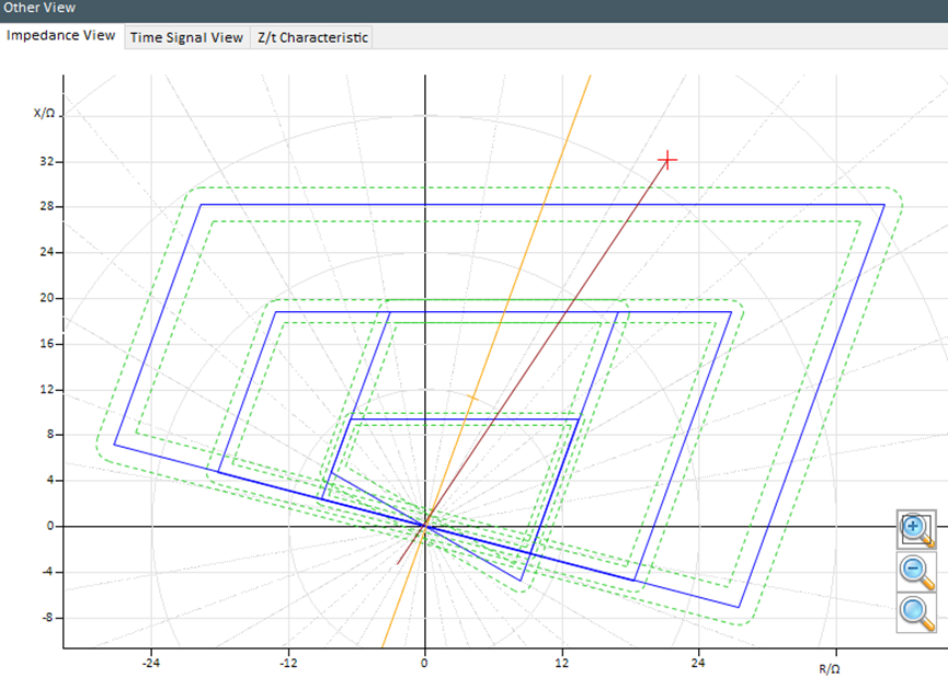
Options include circle, concentric circle, and polygon templates. Click to instantly generate an R/X characteristic curve (e.g., blue quadrilateral), ideal for standard distance protection schemes.
(2) Real-Time Sync: Parameter updates reflect instantly in the curve
Each curve segment's R (resistance), X (reactance), angle, and direction can be configured in the component list. Adjusting any parameter instantly updates the graphical display (e.g., rotation of an orange line), ensuring alignment between settings and visualization.
(3) Curve Comparison: One-glance fault assessment
The chart can display both the protection boundary (e.g., blue) and fault impedance trajectory (e.g., orange). If the trajectory enters the boundary (e.g., orange line intersects blue polygon), it indicates the fault is within the protection zone and should trip. This graphical comparison is more intuitive than raw values, making fault analysis significantly easier.
With the characteristic chart, engineers can visually assess:
Is the fault within the protection zone?
Does the action time meet the requirements?
Do the settings need adjustment?
The visualized curve transforms protection performance from abstract to concrete, supporting both setting verification and fault diagnosis efficiently.
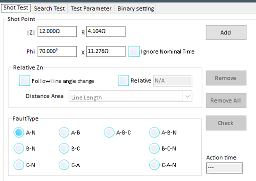
KINGSINE's distance module integrates setting verification, automatic search, and fault simulation into a closed-loop workflow:
Input Settings: Import system parameters (line length, PT/CT wiring) and protection zone definitions (Zone I/II/III impedance and time).
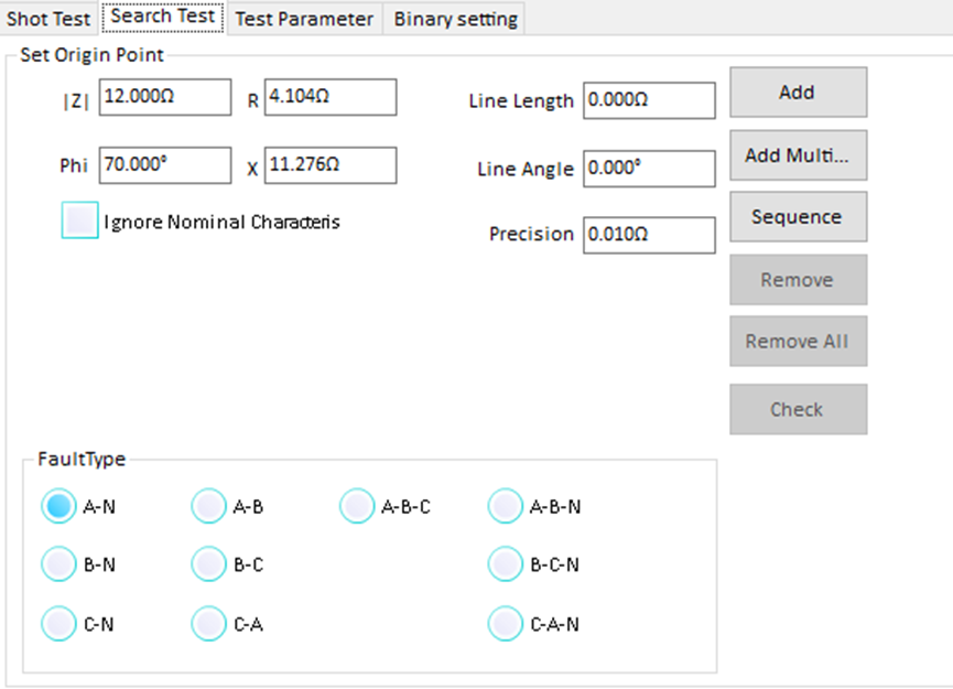
Search Mode: Use point test to manually define impedance Z and angle, or click on the characteristic graph to auto-scan operating boundaries (supports uni-/bi-directional scan, adjustable resolution).
Curve Comparison: Visually compare search results with the custom-defined protection boundary to evaluate setting correctness.
Fault Simulation: Simulate various fault types (single-phase, double-phase, phase-to-phase, three-phase short circuit) to verify protection response under real-world scenarios.
This workflow ensures accurate settings, clear operation boundaries, and reliable fault response, minimizing risks of unwanted operation or protection failure.
1. New Device Setting Commissioning
During factory testing or site installation, use the KINGSINE module to:
Input site-specific line parameters (75 km, 75°), PT/CT configuration (line side).
Set KL=0.667, KM=0.667 (zero-sequence compensation factors).
Define protection zones (e.g., Zone I: 10Ω, 50 ms).
Use auto-search to verify that all zones operate within defined boundaries.
2. Periodic Setting Validation in Operation
As per national standards, protection settings must be validated annually:
Import prior protection zone settings (KRT files).
Automatically verify each zone's operating impedance and time.
Compare with error tolerance (e.g., 5% time error).
Generate a pass/fail report to support O&M decision-making.
More Accurate: Full parameter matching, flexible compensation, precise error limits eliminate misoperations.
Faster: Batch zone testing and automated search reduce test time from hours to minutes.
More Intuitive: Visual custom curves clarify boundaries at a glance, easing analysis.
Fully Compliant: Meets IEC and DL standards with traceable test reports to mitigate compliance risk.
With its focus on accurate setting verification and intuitive curve visualization, the KINGSINE KRT relay testing software Distance Protection Module tackles the key concern of protection engineers—setting correctness. From parameter input to zone verification, error control to graphical analysis, it provides a one-stop solution to ensure distance protection settings are properly configured, thoroughly tested, and reliably operated.
With KINGSINE, distance setting verification evolves from a labor-intensive task into a precision-driven process—ensuring your protection boundaries remain robust and dependable.