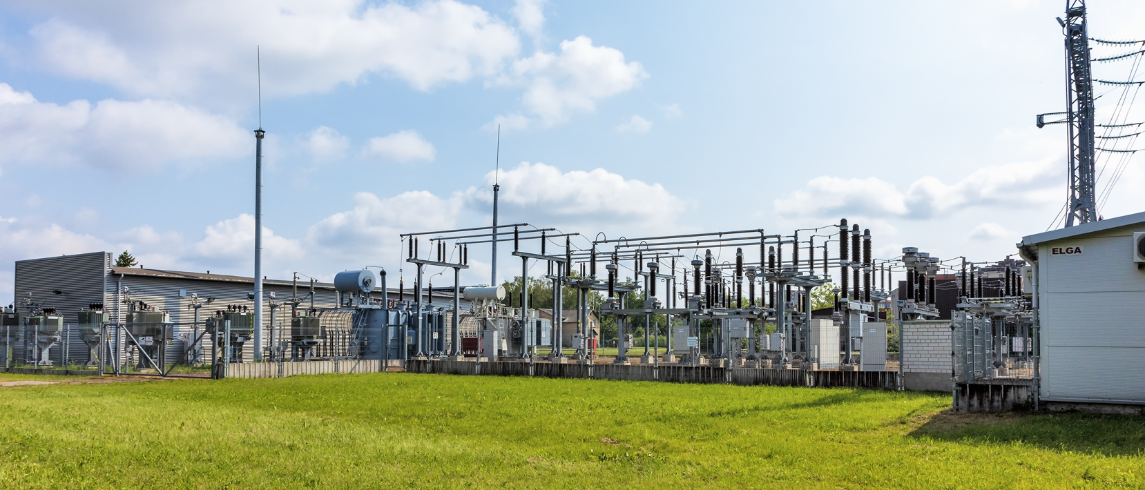
In modern power systems, substations are critical hubs. They not only perform the functions of energy conversion, distribution, and transmission, but also serve as a core link in ensuring the secure and stable operation of the grid. As power systems continue to expand in scale and grow in complexity, ensuring the safety and reliability of substation equipment has become a key topic in both research and practice.

Among the many relay protection methods, overcurrent protection is one of the most common and fundamental approaches used in substations. Owing to its wide application, relatively simple principle, and reliable performance, overcurrent protection is indispensable. When short circuits, overloads, or other abnormal conditions occur, it can act within a very short time to isolate the faulty component, prevent the incident from spreading, and ensure the safe supply of power.
This article provides a comprehensive overview of overcurrent protection in substations, covering its components, working principle, setting calculations, operational issues and solutions, as well as future development trends.
A complete overcurrent protection system typically consists of three main parts: current transformers (CTs), protective relays, and protection devices. These work together to acquire, process, and act upon current signals.
In high-voltage and high-current systems, direct measurement is not feasible. CTs reduce the high primary current to a smaller secondary current, making it suitable for measurement and protection devices.
Working principle: The primary winding is connected in series with the protected equipment, while the secondary winding is connected to relays or protection devices.
Key parameters: (1). Ratio: Determines the relationship between primary and secondary currents. (2). Accuracy class: Defines the precision of measurement and protection. (3). Saturation characteristics: Indicates whether the CT output remains accurate under high fault currents.
In practice, if a CT saturates, the secondary waveform may be severely distorted, leading to false trips or failure to trip. Therefore, when selecting CTs, it is essential to consider rated burden, fault current, and protection sensitivity.
The relay is the executive core of overcurrent protection. It evaluates input current signals and issues trip commands to the circuit breaker.
Electromagnetic relays: Simple in structure, but with lower accuracy and slower response.
Static relays: Use electronic components for signal processing, providing faster operation, higher accuracy, and better immunity to interference.
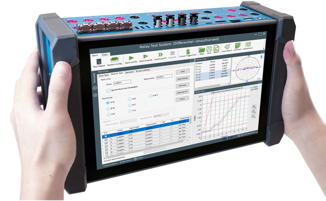
Relay testing: Regular testing with a protection relay tester is crucial to simulate fault conditions, verify relay performance, and ensure reliability.
Routine maintenance involves checking whether relays operate correctly under simulated overcurrent. Protective relay test sets are professional tools that simulate fault currents, feed them into the relay, and confirm if the device responds as expected.

With advances in microprocessor-based protection, modern overcurrent protection devices are increasingly integrated and intelligent. They not only acquire and analyze current signals in real time, but also provide:
Data processing and fault detection: Built-in algorithms accurately identify overcurrent conditions.
Communication: Exchange information with SCADA and monitoring systems.
Self-diagnostics: Monitor hardware and software status with alarms.
Multifunctionality: Support overcurrent, overvoltage, earth fault, differential, and other protections in a single device.
These intelligent devices not only improve reliability, but also lay the foundation for automation and smart grid development.
The basic principle is simple: when current exceeds a preset threshold, the protection operates to isolate the fault. Based on operating time characteristics, overcurrent protection is generally classified into definite time and inverse time types.
Principle: When current exceeds the setting, a timer is started. After a fixed delay, the trip signal is issued.
Features: Operation time is independent of fault current magnitude. Settings are simple and operation is reliable.
Applications: Suitable for systems requiring time-graded coordination between upstream and downstream protections.
Example: In a 110 kV substation’s 10 kV feeder, the overcurrent protection is set to operate at 5 A with a 1.5 s delay. If a fault current of 8 A persists, the breaker trips after 1.5 s.
Principle: The operation time is inversely proportional to fault current—the higher the current, the faster the trip.
Advantages: Allows temporary overcurrent during light overloads, while ensuring rapid disconnection during severe faults, matching equipment thermal limits.
Applications: Commonly used for motor protection and feeder protection requiring precise time coordination.
Example: A large motor may run briefly under minor overload, with longer delay to avoid nuisance trips. In case of a short circuit, however, the relay acts almost instantaneously.
Accurate settings are key to ensuring sensitivity and reliability.
A typical formula is:

Where:
Krel = Reliability factor (1.2–1.3) to prevent false trips
Kjx = Connection factor
IL.max = Maximum load current
Kr = Return factor (0.85–0.95)
nTA = CT ratio
In engineering practice, factors such as motor starting currents and load diversity must also be considered to avoid maloperation.
Definite time protection: The “step principle” is applied, where upstream protection has longer delays. A margin of 0.3–0.5 s is maintained between adjacent stages.
Inverse time protection: Curve selection (standard, very inverse, extremely inverse, etc.) depends on equipment characteristics, with parameters calculated accordingly.
Problem: High fault currents cause CT saturation, distorting secondary current and leading to misoperation.
Solutions:
Use CTs with higher saturation withstand capability.
Apply saturation detection and compensation algorithms in protection devices.
Employ digital CTs with extended dynamic range.
Problem: Protection may fail to operate during low-level or remote-end faults.
Solutions:
Introduce restraint characteristics to improve selectivity.
Use high-impedance relays for better response to small currents.
Optimize settings by considering line impedance and load profiles.
With the rapid development of digital and intelligent technologies, overcurrent protection is evolving into a new stage.
Digital CTs output signals directly, eliminating analog distortions.
IEC 61850-based digital substations enable interoperability and data sharing among devices.
Remote testing, online upgrades, and centralized operation reduce costs.
AI-based algorithms: Neural networks and fuzzy logic enable faster and more accurate fault detection.
Condition monitoring and prediction: Big data and online diagnostics allow predictive maintenance.
Adaptive protection: Parameters can be adjusted dynamically according to system operating conditions.
Future protection devices will not remain as standalone modules. Instead, they will integrate with dispatching, monitoring, and O&M systems, forming part of a unified smart grid platform. Through shared data and centralized control, grid automation and reliability will be further enhanced.