Substations are the core nodes of the power system. Their level of automation directly affects the safety, stability, and efficiency of the power grid. While traditional substation automation systems have developed over many years to become mature and reliable, their inherent limitations—such as complex hardwiring, difficulties in information sharing, and poor interoperability—can no longer meet the requirements of modern smart grids.
The emergence of the IEC 61850 standard, along with its core technologies—SV (Sampled Value) and GOOSE (Generic Object Oriented Substation Event)—has completely reshaped substation architecture and driven a profound digital transformation.
Architectural Features:
Hardwiring Dominated: Protection, control, and metering devices are interconnected through a large number of control cables (copper wires). For example, the secondary side of CTs/PTs is directly wired to the analog input ports of protection relays, while breaker commands are transmitted via cables from relays to breaker control boxes.
Analog Signal Transmission: CTs/PTs output analog signals (e.g., 5A/1A, 100V), which are vulnerable to electromagnetic interference and transmission errors over long cable distances.
Information Silos: Each Intelligent Electronic Device (IED) operates relatively independently. Vendor-specific protocols make interconnection difficult, resulting in poor scalability.
Tightly Coupled Functions: Protection, measurement, and metering often require dedicated CT/PT windings, leading to complex primary equipment and high costs.
Key Issues: Complex wiring, high cost, weak anti-interference capability, low coordination efficiency, and difficulties in maintenance and expansion.
Architectural Features:
Network-Based Communication: Following the principle of "intelligent primary equipment, networked secondary equipment", the process layer (CTs/PTs, circuit breakers) and bay level (protection, control IEDs) communicate via a high-speed substation LAN (typically fiber-optic).
Digital Transmission: The breakthrough lies in replacing analog signals and hardwiring with digital messages.
1. SV (Sampled Value): Replaces analog signal cables. Merging Units (MU) sample CT/PT signals, digitize them, and publish the sampled values as multicast messages. Protection and control IEDs subscribe to these SV messages to obtain current and voltage data.
2. GOOSE (Generic Object Oriented Substation Event): Replaces binary hardwiring. Used for highly time-critical information such as trip commands, interlocking signals, and breaker positions. GOOSE messages feature high priority and retransmission mechanisms to ensure reliability.
High-Level Information Sharing: A single MU can publish SV data for multiple IEDs, eliminating "information silos" and reducing the need for additional CT/PT windings.
Strong Interoperability: IEC 61850 defines unified data models and communication services. As long as devices comply with the standard, they can be seamlessly integrated and achieve "plug-and-play" operation.
Core Advantages: Simplified secondary circuits, strong anti-interference capability, full information sharing, flexible configuration, and complete digitalization, enabling advanced applications such as condition monitoring and intelligent diagnostics.
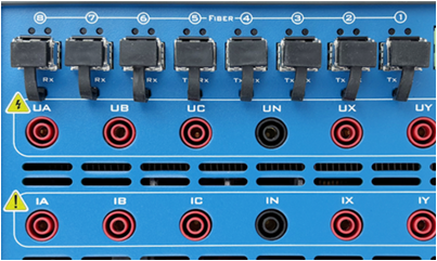
SV plays a key role in process-level digitalization. Its workflow is as follows:
Sampling: The Merging Unit synchronously samples current and voltage values from electronic or conventional CTs/PTs (the latter requiring A/D conversion). Synchronization accuracy is critical and is usually ensured via IEEE 1588 Precision Time Protocol (PTP) or IRIG-B.
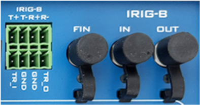
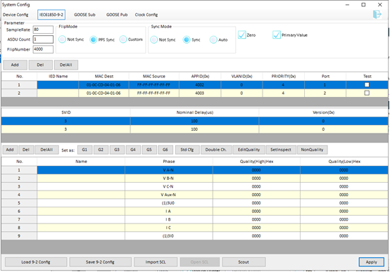
Framing: The MU encapsulates each sampling point (including channel count, quality factors, etc.) into Ethernet frames according to IEC 61850-9-2 (or earlier 9-1/LE).
Publishing: The MU transmits SV messages as multicast frames via the process bus. Any IED subscribed to that multicast address can receive them.
Subscription: Bay-level IEDs (protection, control) listen to multicast addresses. After receiving SV messages, they parse and validate the data, reconstruct waveforms, and use them for logic calculations (e.g., overcurrent protection, power calculation).
Key Parameters:
Sampling Rate: Typically 80 samples per power frequency cycle (4 kHz), though higher or lower rates are possible.
Message Format: IEC 61850-9-2 is the mainstream standard, offering flexible dataset structures.
Transport Protocol: Based on ISO/IEC 8802-3 (Ethernet), typically with VLAN tagging and priority marking to ensure real-time performance.
This technological shift has also revolutionized testing methods.
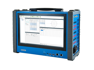
Main Tool: Conventional relay test sets.
Testing Approach:
Hardwired: The test set's analog outputs are wired directly to the relay's analog inputs.
Binary I/O: The test set's binary inputs/outputs are wired directly to the relay's binary terminals.
Focus: Verification of relay logic functions, such as overcurrent settings and operating times. Testing is device-specific.
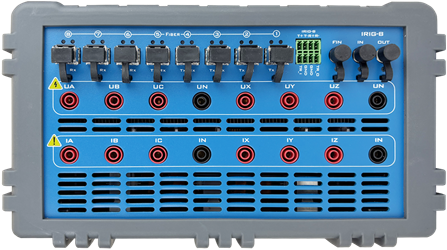
Testing evolves from "point-to-point" to "system-oriented", covering several levels:
a) IED Unit Testing
Tools: IEC 61850-compatible digital test sets, capable of not only simulating analog signals but also publishing and subscribing to SV and GOOSE messages.
Content:
1. SV Subscription Test: Verifies that the relay can correctly receive and process SV messages and respond appropriately (e.g., tripping upon simulated fault conditions).
2. GOOSE Subscription/Publication Test: Ensures IEDs can correctly handle external GOOSE inputs (e.g., interlocking) and publish their own GOOSE outputs (e.g., trip commands).
3. ICD/CID File Import: Test sets can import IED configuration files to automatically configure SV/GOOSE parameters, improving efficiency.
b) System Integration Testing
Purpose: To verify the coordination of the entire system, not just individual devices.
Tools: Network analyzers, digital test sets, and SCD (System Configuration Description) tools.
Content:
1. Communication Conformance Testing: Ensures compliance of IED communication stacks and data models with IEC 61850 standards.
2. SV/GOOSE Network Performance Testing:
(1). Traffic Monitoring: Ensures no packet loss or congestion.
(2). Latency Testing: Measures end-to-end delays for SV delivery and GOOSE trip execution, ensuring protection speed requirements.
(3). Synchronization Accuracy Testing: Confirms MU sampling synchronization errors remain within acceptable limits (typically ±1 μs).
3. Closed-Loop Simulation: Builds a real-time simulation environment including primary system models, MU simulators, and multiple IEDs to test protection performance under complex grid fault scenarios.
c) Operation and Maintenance Testing
Tools: Portable SV/GOOSE analyzers or optical digital multimeters.
Content: During maintenance, engineers can directly access process bus data, "read" SV values like analog signals, or "listen" to GOOSE states, enabling rapid fault location.
IEC 61850 and SV technology have shifted substations from the hardwired "analog world" to the networked "digital world". While this transition offers significant advantages, it also imposes higher demands on design, testing, and operation.
Testing focus has expanded from device-level functional checks to comprehensive validation of communication performance, system coordination, and time synchronization. Mastery of SCD-based system configuration, network traffic analysis, and digital testing tools has become essential for today's power engineers.
This transformation is not only a technological upgrade but also a paradigm shift, laying the foundation for building smarter, more flexible, and more reliable future power grids.